Adjusting Mesh Sizes
The underlying driver for the Automatic Mesh Sizing facility is the geometry. Mesh is automatically concentrated in regions of high curvature and rapid size variation. In certain situations, significant flow gradients in a simple geometry may require that the mesh be finer than assigned by Automatic Mesh Sizing.
An example is a volume constructed in the wake of an aerodynamics study. The volume is simple, so its automatically-defined mesh will be coarse. Because the flow is quite energetic and will have high gradients, a finer mesh is required in the wake region:
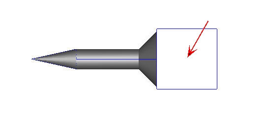
A mechanism is provided that allows for the local adjustment of automatically assigned mesh sizes on volumes, surfaces, and edges after Automatic Sizing has been invoked:
Work Flow
1. Adjust sizes with the Size Adjustment Slider
Set the selection mode (Volume, Surface, or Edge), then select the desired entities.
The slider uses a parametric scale that extends between 0.2 and 5, with a default position of 1.0. This allows the mesh size to be reduced to 1/5th or increased to as much as 5 times the original size. To apply a value that exceeds the minimum or maximum range, (smaller than 0.2 or larger than 5), type the scaling value into the field to the right of the slider.
As the slider is moved, the modified distribution updates dynamically. After deciding on a desired slider position, click the Apply changes button. This ensures that the setting will be available in the replay Macro file (used for rebuilding the mesh distribution and when settings are applied to modified geometry).
The Cancel button will return the slider position to 1--effectively undoing any adjustments made to an entity after either the automatic size specification or since the last Spread Changes command.
Note that the mesh quality constraints embedded in this system may override adjustments that excessively coarsen the mesh. This is done to prevent a mesh definition that will result in a poor-quality or failed mesh.
2. Smooth mesh sizes with the Spread Changes Button
When the Spread Changes button is pushed, all modified settings are resolved with neighboring settings to ensure proper element transitions. The slider position for each adjusted entity resets to 1--the middle of the slider range. This means that the newly assigned size becomes the default size for subsequent adjustments. Note that the slider does not reset when the Apply changes button is pressed.
In general, however, the Spread Changes button should be used sparingly because pushing it initiates a complete recalculation of the mesh distribution. If Spread Changes is not pressed prior to leaving the Meshing dialog, the function will be invoked automatically when the analysis is started or when the analysis is saved.
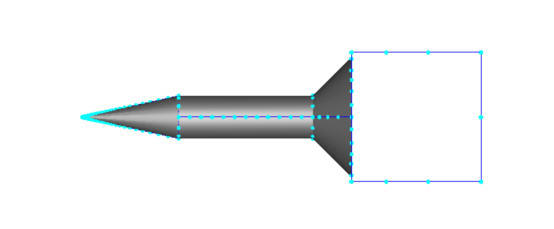
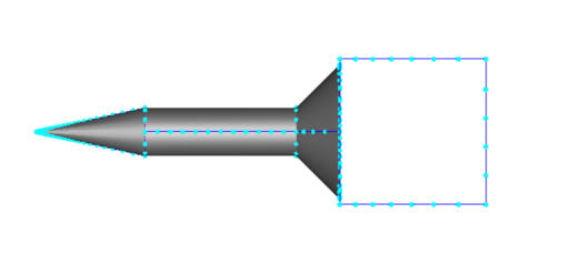
Example of Spread Changes
3. Optional: Apply Uniform Sizing with the Use Uniform Button
A uniform mesh distribution can be applied to an entity by selecting it, and clicking the Use Uniform button. This command modifies the underlying length scales throughout the entity to be the same, based on the smallest length scale on the object.
It is not necessarily persistent, however, and subsequent changes to neighboring entities can cause the mesh to vary again. For this reason, we recommend that Uniformity is applied after other adjustments have been made.
After the Use Uniform button is clicked, the slider will reset to 1. This allows subsequent modification of the size on the entity.
Uniformity can be removed from an entity by selecting it and clicking the Cancel button IF this is done prior to hitting the Spread Changes button. After Spread Changes is clicked, Uniformity cannot be removed directly from the model.
Example of the Use Uniform button
The results are shown. The original mesh size is shown on the left. The mesh refined to 0.4 is shown on the right:
General Guidelines
This is a summary of the areas in which manual refinement is often recommended:
Distributed Resistance Regions
In general, three elements through the width of a distributed resistance is recommended for best accuracy. For very thin geometry, this may not be practical.
Internal Fans
The mesh distribution in an internal fan should be adjusted to produce at least two elements in the flow direction of the fan.
Wake Regions
As illustrated above, geometry constructed in high-velocity or high-gradient regions should be refined to ensure adequate representation of the flow physics. In some models, a uniform mesh distribution is useful, especially if the default distribution has a lot of variation. Use the Use Uniform button to apply a uniform mesh.
Motion Path
The mesh distribution in the path of a moving object should be refined. This will allow the velocity and pressure distributions to be calculated properly and prevents mesh “bleed-through.” A uniform mesh is often recommended for the motion path, and is prescribed using the Use Uniform button.
Rotating Regions
A uniform mesh should be used when possible on a rotating region. This is recommended because the default automatic sizing will often cause the initial position of the impeller to influence the mesh on the rotating region, potentially causing problems as the impeller rotates. With a uniform mesh on the region, the mesh will not skew the results.
Play Macro
The relationship between size adjustment on entities and the recalculation of neighboring length scales when the Spread Changes button is selected is quite complex. This makes it potentially difficult to exactly recreate a mesh distribution on a complicated model if multiple adjustments occurred.
To facilitate this process, a log file containing all size adjustment commands is automatically recorded when Automatic Sizing is invoked. Every size adjustment and instance of the Spread Changes button is recorded, and can be played back to exactly reproduce a mesh distribution on a given model.
The file is first created when the Apply changes button is clicked after adjusting a size, and commands are automatically appended as they are issued. When the Delete All button is hit, the mesh distribution is removed from the model, and the Play Macro button becomes active. Click it to re-assign the mesh distribution to the model.
Invoke the file by clicking the Play Macro button. The button is available when a mesh distribution containing adjustments did exist, but was deleted. It is also available if the distribution is deleted, and the Automatic Size button is pressed, and will overlay saved adjustments over the default mesh distribution.
This assigns the exact mesh distribution that was previously saved. Note that a specific macro should only be applied to the same geometry. Applying this file to a different geometry will lead to unexpected results.
The file is named with the analysis name with the extension “.meshlog”. To use a mesh log with another analysis based on the same geometry, copy the meshlog file to the new analysis name, and click the Play Macro button.
The macro file is stored with the analysis file, and a copy is extracted to the working directory when the analysis is opened. If a macro file exists for that analysis, it will be overwritten by the one extracted from the analysis file. When an analysis is closed, the macro file in the working directory is copied into the analysis file. If there is no macro file in the working directory, then any macro file in the analysis file will be deleted. If the analysis is closed but not saved, the external copy of the macro file is not packed into the analysis file.
A macro file can be deleted through the Autodesk® CFD interface in these three ways:
Click the Automatic Size button when the model has a distribution that has been adjusted with the Size Adjustment slider.
This resets the distribution throughout the model to the default, deleting the macro file.
After deleting the mesh distribution, click the Automatic Size button, and adjust sizes.
The first click of the Automatic Size button can be followed by clicking the Play Macro button to overlay it on the model. If, however, sizes are adjusted after hitting the Automatic Size button but prior to hitting the Play Macro button, the macro will be removed because a new adjustment strategy is assumed.
After deleting the mesh distribution, click the Automatic Size button twice.
As mentioned, the first click of the Automatic Size button can be followed by clicking the Play Macro button. If the Automatic Size button is clicked again, however, the macro is removed.