Creating the Flow Volume in Pro/Engineer
Many models constructed in Pro/Engineer consist of just the physical solids (the pipe wall, for example). There are three methods of creating the internal flow volume:
- Manually create it using tool within Pro/Engineer.
- Create capping geometry at the openings. This method is described in this topic.
- Create the void fill in the Autodesk® CFD environment using the Geometry Tools.
Example of cap creation in Pro/Engineer
In the following example, the pipe wall and two internal parts were created in Pro/Engineer:
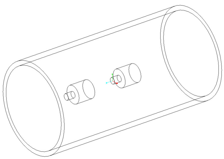
To prepare this for a flow analysis, simply add a cap to both ends of the pipe:
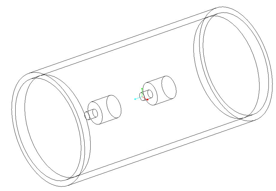
The Pro/Engineer geometry shown above consists of five parts: the pipe wall, the two internal components, and the two end caps. In this example, the caps are constructed using the inner diameter of the pipe wall, and extruded into the pipe. Alternatively, the caps could have been extruded out of the pipe, or have been built using the outer diameter of the pipe wall.
When brought into Autodesk® CFD, the internal volume is automatically created:
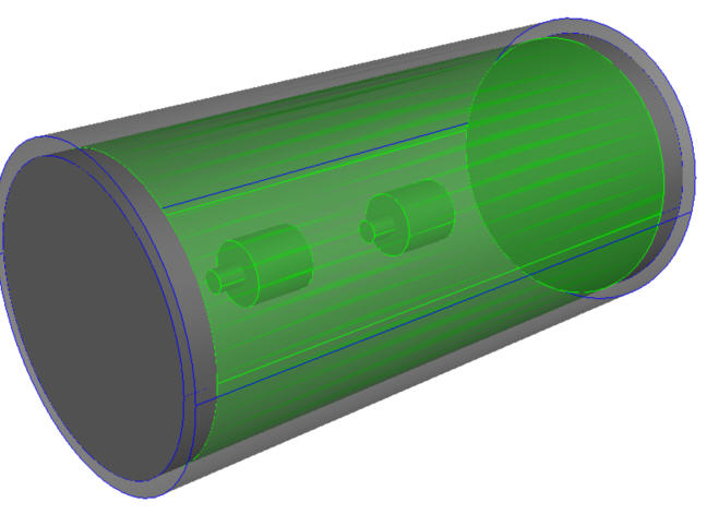
The two internal parts are automatically cut from the newly created flow volume.