Boundary Conditions
Boundary conditions define the inputs of the simulation model. Some conditions, like velocity and volumetric flow rate, define how a fluid enters or leaves the model. Other conditions, like film coefficient and heat flux, define the interchange of energy between the model and its surroundings.
Boundary conditions connect the simulation model with its surroundings. Without them, the simulation is not defined, and in most cases cannot proceed. Most boundary conditions can be defined as either steady-state or transient. Steady-state boundary conditions persist throughout the simulation. Transient boundary conditions vary with time, and are often used to simulate an event or a cyclical phenomena.
Initial conditions are a different type of condition that are active only at the beginning of the simulation. For more about initial conditions, click here.
Boundary Condition Workflow
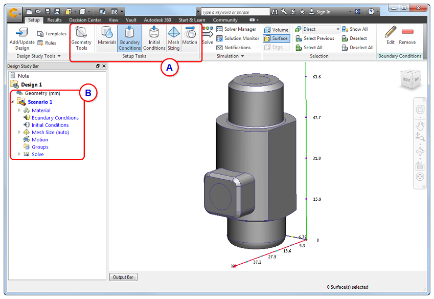
To begin, enable the Boundary Condition task from either the Setup (tab) > Setup Tasks (panel) (A) or from the Design Study bar (B):
To work close to the model:
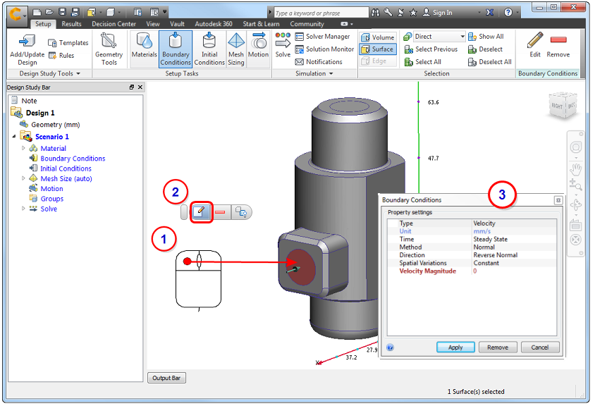
- Left click on the model entity (surface or part).
- Click the Edit button on the context toolbar.
- Specify settings in the Boundary Conditions quick edit dialog.
Alternatively, right click on the model entity or branch on the Design Study bar, and click Edit...
To work away from the model:

- Left click on the model entity (surface or part) to select it.
- Click Edit in the Boundary Conditions context panel.
- Specify settings in the Boundary Conditions quick edit dialog.
To assign the boundary condition in the quick edit dialog:
- Set the Type of condition.
- Set the Units (if applicable).
- Set the Time Variation (Steady State or Transient).
- Apply condition-specific settings such as Normal or Component for Velocity or Static or Gage for Pressure. Change the flow direction for velocity, volume flow rate, or mass flow rate.
- Specify the value.
- Click Apply.
To define and then apply a boundary condition
An alternative workflow is to create a boundary condition before applying it to the model.
- Click Edit on the Boundary Conditions context panel. Alternatively, right click on the Boundary Conditions branch of the Design Study bar, and click New BC....
- Define the boundary condition in the Boundary Conditions quick edit dialog, and click Apply.
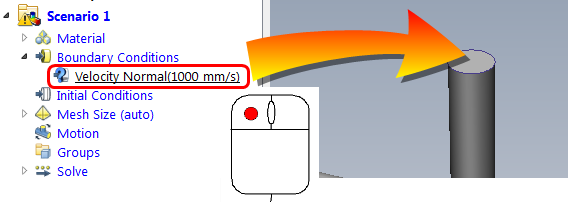
- Drag the unassigned setting from the Design Study bar onto the model entity:
To Remove a Boundary Condition
To remove a boundary condition from a specific entity (several ways):
- Left-click on an entity, and click the Remove icon from the context toolbar. (This removes conditions in the order they were applied.)
- Expand the Boundary Condition branch in the Design Study Bar, right click on a specified condition, and click Remove.
- Select the entity, and click Edit from the Boundary Conditions context panel. On the quick edit dialog, set the Type to that of the condition to be deleted, and click Remove.
To remove a single boundary condition from multiple entities:
- Expand the Boundary Condition branch in the Design Study Bar.
- Right click on the condition to remove.
- Click Remove.
To delete all boundary conditions:
- Right click on the Boundary Condition branch of the Design Study bar.
- Click Remove All.
Graphical Indications
Results Legend
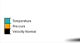
A colored stripe is drawn on every entity with an assigned boundary condition. Each boundary condition type has a different color stripe. A legend in the lower left corner of the Graphics window shows this correspondence for the conditions applied to the model:
Entities with multiple conditions have multiple stripes.
Design Study Bar
All conditions are listed below the Boundary Conditions branch of the Design Study bar:

Selection List
To see the conditions applied to a specific entity, enable the Selection list, and select the entity:

To enable the selection list, click the toggle in the Quick Access toolbar:
