Physical Boundaries
This topic describes many of the types physical boundaries found in CFD simulations, and relates them to the available boundary condition types.
For more about applying Boundary Conditions
Inlets
There are three primary classifications of inlet conditions: flow, temperature, and scalar (for mixing). The specific type of boundary condition to apply depends on the type of analysis (incompressible or compressible):
Incompressible:
For incompressible flow, specify either the pressure or velocity components. Specifying both velocity and pressure over-constrains the problem and numerical difficulties can be expected.
Specify one of the following boundary condition types to inlets:
- Normal Velocity or non-zero velocity components
- Gage static pressure
- External fan: the inlet flow rate varies with the pressure drop through the device
- Volumetric flow rate
- Mass flow rate
To include swirl (an out of plane velocity component) in a 2D axisymmetric analysis, specify the third component of velocity (usually the z-component).
It is not necessary to specify turbulence quantities at any inlet. The inlet turbulence intensity used for calcuating the turbulent kinetic energy and turbulent energy dissipation is set in the Turbulence dialog on the Solve dialog.
Compressible:
For compressible or supersonic inlets, we often specify both velocity and pressure. This is necessary only if the inlet is nearly sonic or faster. Because compressible analysis strategy is very sensitive to the physics that are simulated, please see the compressible section for information about applying boundary conditions.
For heat transfer analyses, specify the temperature at all inlets.
To simulate mixing, specify a scalar value at all inlets, even if the value is zero.
Outlets
At the outlet, Autodesk® CFD assumes that fully developed profiles exist for the flow quantities, U, V, W, T, K,  . This condition implies that the gradient of these quantities normal to the outlet boundary is zero. This condition is applied automatically in Autodesk® CFD.
- The recommended (and most convenient) outlet condition is a gage static pressure equal to 0. No other boundary conditions should be applied to an outlet with a Pressure = 0 condition.
- If the velocity, mass flow rate, or volumetric flow rate is known at an outlet, then any of these conditions can be applied to the outlet. Be sure to specify a pressure at the inlet.
- An external fan boundary condition pulling flow from the model can be applied to an outlet.
- If the outlet flow is supersonic, the Unknown boundary condition is often the recommended condition. Unknown is a “natural” condition meaning that such an outlet is simply open, and no other conditions (velocity or pressure) are enforced.
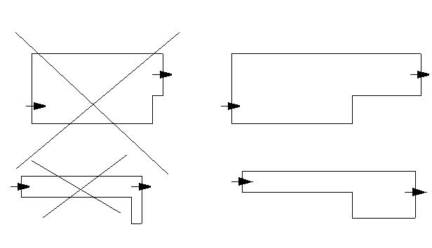
Outlet conditions should be positioned far enough downstream from sudden turns or contractions to allow the flow to reach a fully developed state, which is the condition assumed by Autodesk® CFD. Furthermore, if the outlet is too close to a sudden expansion, flow will come back in through the outlet. This may cause convergence difficulties:
Walls
Automatic Wall Specification sets wall conditions automatically on all surfaces that are not defined as inlets, outlets, symmetry, slip, or unknown.
It is not necessary to set a zero velocity (no-flow) condition at any fluid/solid interface. Wall turbulence conditions are set automatically by Autodesk® CFD.
The boundary condition types for heat transfer analyses are:
- Temperature
- Heat flux
- Film coefficient
- Radiation condition
It is generally not recommended to apply more than one heat transfer boundary condition to a wall.
Wall with no heat transfer conditions are considered to be insulated.
Symmetry and Slip Conditions
To simulate a slip or a symmetry condition, apply the Slip/Symmetry boundary condition. This condition prevents flow from crossing the boundary, but allows the flow to move along the boundary.
Autodesk® CFD assumes that the gradients normal to the symmetry plane for the scalar quantities T, K, are zero.
Periodic Boundaries
Unlike all of the previous boundary conditions which operate on particular solution variables, periodic boundaries are actually a geometric condition which affect all of the solution variables identically.
In particular, all solution variables are identical at periodic nodes; i.e., the value at the secondary node is exactly the same as that at the primary node. Periodic boundary conditions can be used in geometrically similar geometries like multi-bladed vaned diffusers, for example. They allow a greatly reduced problem size.