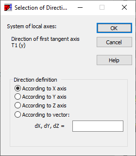
Results are presented in the local coordinate system so a local system direction can be selected. Click Direction... on the Detailed tab of either the Maps on Solids or Solid Cuts dialog to do so.
In the Selection of Direction dialog two local system definitions are available.
- Cartesian. The local element system will be adopted according to the orthogonal system defined globally by a user for all solids. The following coordinate options are available: according to X and Y axes, according to X and Z axes, according to Y and Z axes and according to the user defined vectors.

- Cylindrical. if this option is selected, then, the local element system will be adopted according to the cylindrical system defined globally by a user for all solids The following options are available: options that allow determining the system beginning (a point or node) and options permitting definition of the vertical axis (axes X, Y, Z or a vector). The components of results for solids xx, yy and zz in the cylindrical system of coordinates signify correspondingly the following directions: radial, circumferential and vertical (r, φ, z).

When defining a direction for cuts through solids (when the "Internal forces in the table" option is switched on in the Detailed tab) the Selection of Direction determines a direction of the first tangent axis T1 according to a selected vector or direction of the main coordinate system.

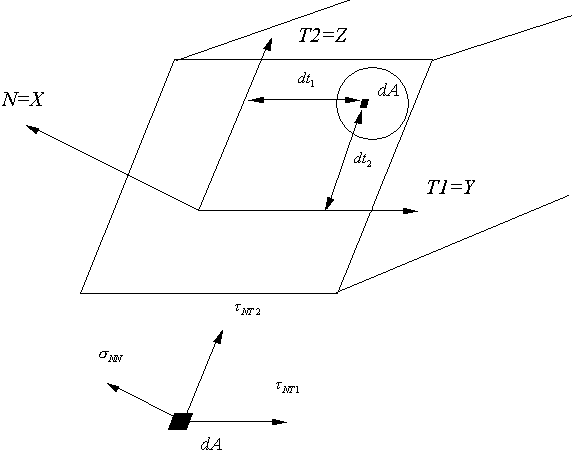
The coordinate system in the cross section is as follows.
- N axis - Normal to the cross section plane - x axis
- T1 first tangent axis to the cross section plane - y axis
- T2 second tangent axis to the cross section plane - z axis.
With the directions listed the following stresses are associated: σNN, τNT1 and τNT2.

See also: