Materials: Chips and other Components
In this step we assign silicon to the chips.
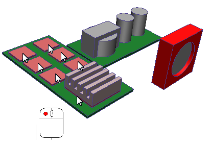
1. Select the seven chips. They are all on the same PCB:

Note: Don't forget the larger chip under the heat sink. (You may have to hide the heat sink to see it.)
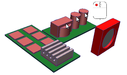
2. Select the two capacitors and the transformer.

3. Click Edit from the Materials context panel:

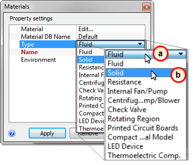
4. On the Materials quick edit dialog, select the material type:
- a. In the Type row, click in the right-side column.
- b. Select Solid.

5. From the Name menu, select Silicon.
![]()
6. Click Apply.
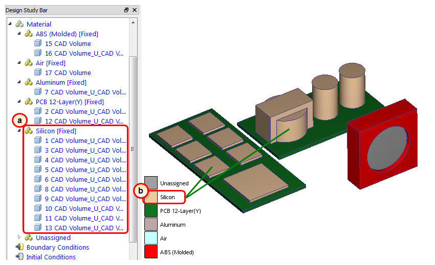
What it should look like...
7. To verify that the Silicon material is properly assigned, check the Design Study Bar and the part coloring:
- a. On the Design Study bar, confirm the material assignment for the Silicon parts.
- b. The chips should be colored to correspond to the Silicon color in the legend.

Note: Autodesk® CFD also has a compact thermal material that uses a two resistor model to simulate the thermal performance of integrated circuits. To keep this tutorial simple, however, we assigned a silicon solid material instead.