Basic Model Interactions
This video and topic explore some of the ways you can interact with your Autodesk® CFD models. To help you to quickly learn Autodesk® CFD, you might want to book mark this page for easy reference.
Video Notes:
Navigate with the Mouse (Rotate/Zoom/Pan)
These are the basic ways to move the model with the mouse.
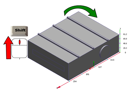
To rotate, press Shift and the middle mouse button, and move the mouse:
To zoom, roll the mouse scroll wheel:

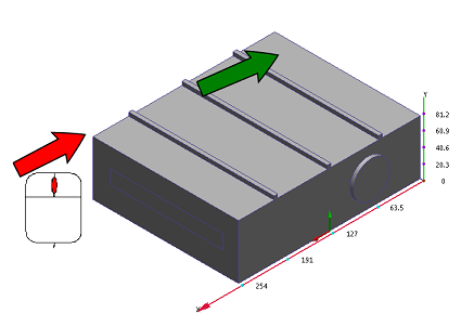
To pan (move), hold the middle mouse button, and move the mouse:
To learn more about navigating with the mouse, click here.
Navigate with the Navigation Tools
You can also move the model with the navigation tools embedded directly within the user interface:
ViewCube:

To rotate the model, position the mouse over the ViewCube and press the left button while you drag the mouse. To change the model orientation, click any face, edge, or corner on the ViewCube.
To learn more about the ViewCube, click here.
Navigation toolbar:

The navigation toolbar is a collection of orientation tools. It is located on the right side of the graphics window. You can these tools to pan, zoom, and rotate the model.
To learn more about the Navigation toolbar, click here.
Set the Selection Mode
There are times when you will need to change the type of object that can be selected:
From the Setup tab:

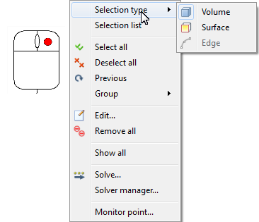
From the right click mouse menu:
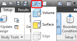
From the Quick Access toolbar...
The cursor indicates the current selection mode:
Volume:  Surface:
  Edge:
Edge: 
Selection Coloring
Autodesk® CFD uses color coding to help with the selection process…
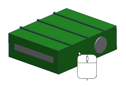
When you hover over a part or surface in the Setup tasks, it turns green:
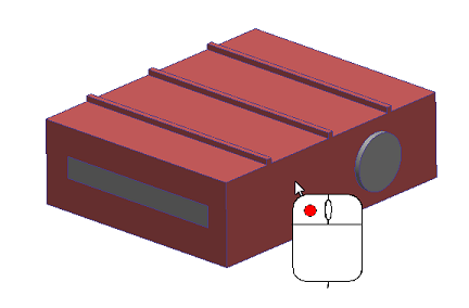
Select the object by left clicking on it. It turns red:
If you hover over a selected object, it turns yellow:
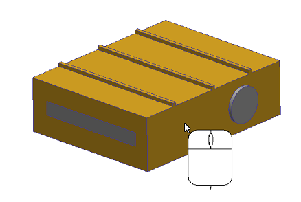
To deselect an object, left click on it.
Part and Surface Visibility
In many cases, it is helpful to hide a part or surface to access an internal component.
To hide an object: Hover over it, and press Ctrl and the middle mouse button:
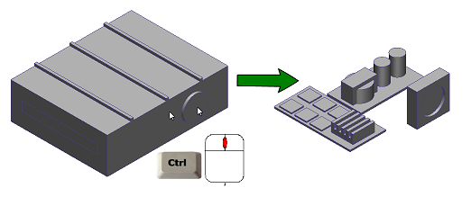
To select an object and then hide it, left click on it, and click Hide from the context toolbar: ![]() . Note that the part is selected because you left clicked on it. This is useful when you want to assign the same setting to external and internal parts:
. Note that the part is selected because you left clicked on it. This is useful when you want to assign the same setting to external and internal parts:
To show all parts: Press Ctrl and middle click off the model in the graphics window.
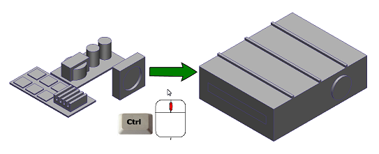
Alternatively, left click off the model, and select the Show all icon:  . You can also right click off the model, and select Show All.
- For the Setup tasks, to change the type of entity that is hidden, change the Selection Mode.
- For the Results tasks, volumes are hidden by default. To change to surfaces, click (View tab > Appearance panel > Surface Blanking).
To learn more about controlling part and surface visibility, click here.
Model Appearance
By default, the model appears shaded, like this:
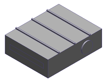
To show the model as an outline or as transparent, select from the Visual Style menu in the Quick Access toolbar:
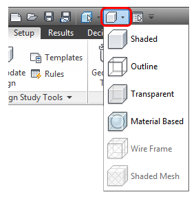
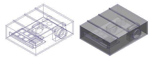
Alternatively, select from (View tab > Visual Style).
To change the appearance of an individual part, right click on it, and select from the menu:
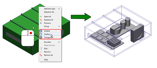
To learn more about controlling the appearance of your model, click here.
Check your work
The Design Study Bar shows all assigned settings under the appropriate branch:
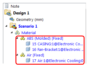
Graphical cues and a corresponding legend show where settings are applied:
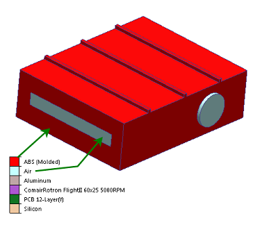
Tooltips show the values of applied settings. Hover your mouse over the part or surface to view the tooltip:
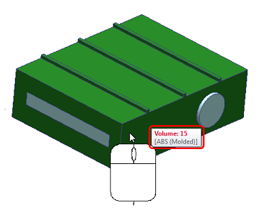
Next Step
The next video is about the Autodesk® CFD user interface.
Alternatively, you can return to the Quick Start home page to watch a different video, do a tutorial, or start applying what you've learned.