Visualize the Flow and Temperature Together
In this step, we create a three dimensional view of the flow and temperature results.
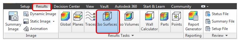
Click Results > Results Tasks > Iso Surfaces.
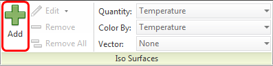
Click Add from the Iso Surfaces context panel.
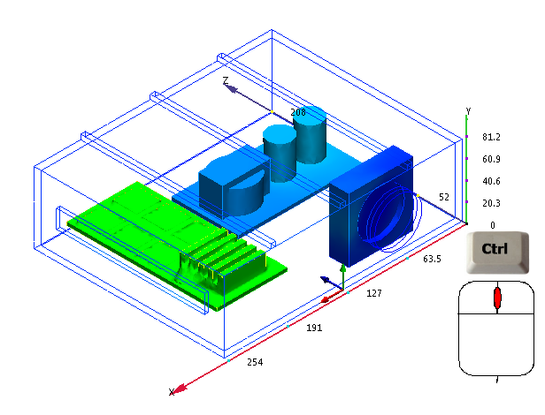
If the casing is not showing, resume it by holding Ctrl and middle clicking anywhere off the model.
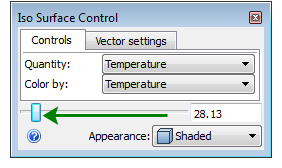
 Note: This is a surface with a uniform value. It shows everywhere that has the same value of temperature.
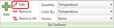
To change the value, click Edit from the Iso Surfaces context panel.
To see more detail, drag the slider to about a quarter of the way from the left edge.
You should see this:
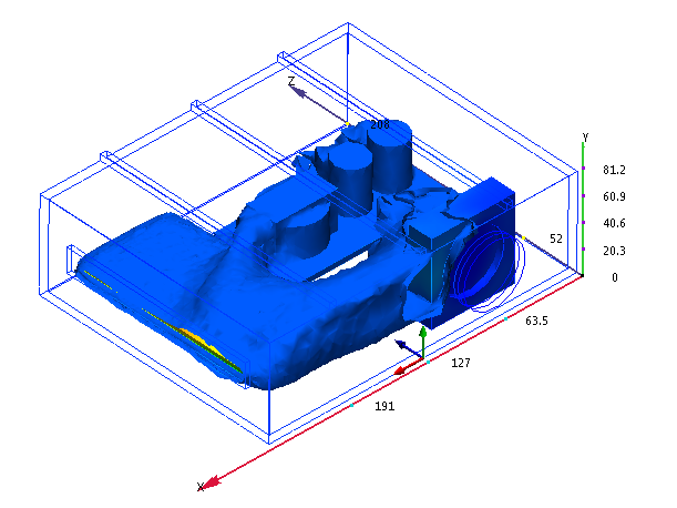 Note: The iso surface is very useful for locating the min and max temperatures.
Next we combine the flow and temperature results:
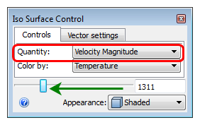
Change the Quantity to Velocity Magnitude.
To see more of the low-velocity flow, drag the slider to the left. You should see this:
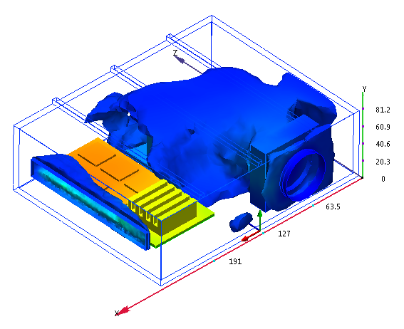
This plot maps the temperature distribution onto the velocity iso surface. Drag the slider to change the displayed value of velocity magnitude.
To show vectors, click the Vector settings tab, and select Velocity Vector.
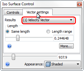
You should see this:

This view contains a lot of information. It tells us that after flowing over the transformer and capacitors, the air impinges on the back wall of the enclosure. The moving air removes heat from the components before flowing over the chips.
We can see that the flow barely removes enough heat from the small chips to keep their temperature below the safety threshold of 60 °C.
Wrap up
Nice job! In a few short minutes you created a complete 3D electronics cooling simulation.
After launching from CAD, you assigned the settings, ran the simulation, and visualized the results in several ways. The result is a thorough understanding of the effects of the three-dimensional flow field and temperature distribution within the enclosure.
Next Steps
To return to the Quick Start home page, click here.
For additional resources to help you along your journey with Autodesk® CFD, click here.
To connect with other Autodesk® CFD users and experts in our Discussion Groups, click here.