Visualize the Flow with Iso Surfaces
In the previous step, we used Results Planes to view results in two dimensions. In this step, we use Iso Surfaces to view the results in three dimensions.
1. To start, click Remove from the Planes context panel.

2. Create an iso surface by clicking Results > Results Tasks > Iso Surfaces.

3. Click Add from the Iso Surfaces context panel.

You should see this:

This is a surface with a uniform value. It shows the places in the model that have the same value of velocity magnitude.
4. To change the value, click Edit from the Iso Surfaces context panel.

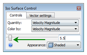
5. On the Iso Surface Control dialog, drag the slider to a quarter of the way from the left end for a more interesting view.

You should see this:

This is a three dimensional view of the flow distribution.
Iso surfaces are a great tool for AEC simulations because they clearly communicate the flow distribution in the space. Results planes capture a two dimensional slice of the flow, but iso surfaces capture the full, three-dimensional view.
In this case, we see that at the specified velocity, a large volume of air moves under the desk and behind the occupant.