Boundary Conditions: Supply
In this step, we define the flow rate at the supply.
Click Boundary Conditions from the Setup tab:
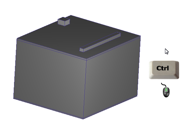
Make sure all parts are visible by holding Ctrl while middle clicking anywhere off the model.
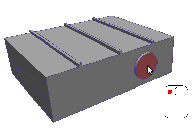
Left click the supply surface.
Click Edit from the Boundary Conditions context panel:

On the Type row, select Volume Flow Rate.
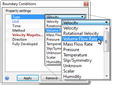
On the Unit row, select ft3/min.
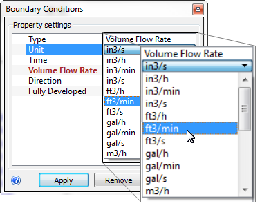
On the Volume Flow Rate row, enter 150.

Click Apply.
Note: We next apply the supply temperature condition:To select the supply surface again, click Setup (tab) > Selection (panel) > Select Previous.

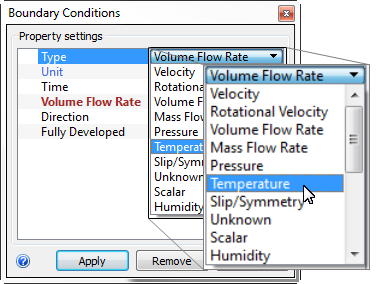
Click Edit from the Boundary Conditions context panel:
On the Type row, select Temperature.
Verify the Units are Fahrenheit. On the Temperature row, enter 65.
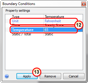
Click Apply.
What it should look like...
To verify that the two boundary conditions are properly assigned, check the Design Study Bar and the colored stripes on the supply surface:
On the Design Study bar, confirm the values for both conditions. (You might have to drag the right edge of the design study bar to see both conditions...)
The two stripes on the supply face should correspond to the boundary conditions types in the legend. (The stripes are thin, so you may need to zoom in to see them.)
