Use the Layout tab to create a block component for a label style.
From the Create Component list ![]() , click
, click ![]() to create a new block component.
to create a new block component.
General
- Name
-
Specifies the name of the block component.
The default name, such as “Block.1,” is the component name with a numeric increment. If the block component exists in a parent label style, then the name cannot be edited.
- Visibility
-
Specifies whether the block component is visible in the label style.
- Used In
-
Specifies whether the component is visible in tag mode, label mode, or both. Select a mode on the General tab in the Label Style Composer.
- Label Mode: Displays the block component when Display Mode (on the General tab) is set to Label.
- Tag Mode: Displays the block component when Display Mode is set to Tag.
- Label and Tag Modes: Displays the block component regardless of the display mode setting.
Note: If a label style type does not support tables, then this control is not available. - Anchor Component
-
Specifies a reference object for positioning the block component. You can select <Feature> (which is the object being labeled) or another existing label component.
- Anchor Point
-
Specifies the location on the Anchor Component where the block component is attached.
- When <Feature> is the Anchor Component, Label Location is the only option available. This option places the anchor point at the location where the label is attached to the object.
- When the Anchor Component is another label component, you have a choice of anchor points depending on whether the anchor is a text, block, tick, line, or direction arrow component.
Block
- Block Name
-
Specifies the block to use in the block component.
Click the Value column, and then click
 to open the Select A Block dialog box.
 In the Select A Block dialog box, click
 to open a Viewer in which you can use standard AutoCAD viewing tools to preview the block. Note: The block must exist in the current drawing.
 - Block Height
-
Specifies the height to which the block is scaled to fit. The block’s extents in the X direction are used for scaling the height. The block’s aspect ratio is maintained when scaled.
- Rotation Angle
-
Specifies the angle for the block component. Enter a positive or negative value, or click
 to select an angle in the drawing.
 The angle direction is always counterclockwise, and the zero (0) direction is determined by the anchor component type.
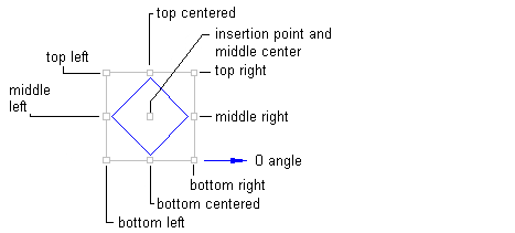
- Attachment
-
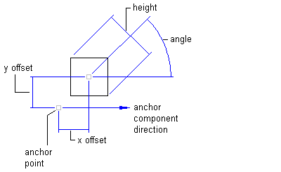
Specifies the location on the block component that is attached to the anchor point. Attachment points are calculated based on a rectangle that encompasses the block, the size of which is determined by including the Gap value specified in the Border category. The following illustration shows block attachment points:
- X Offset
-
Specifies the offset distance between the attachment point and the anchor point in the X direction (zero angle direction).
The X direction is determined by the object to which the block component is anchored. If the block component is anchored to the label insertion point, then the X direction is determined in relation to the following Orientation Reference setting on the General tab:
- Object: Calculates the X direction by examining the object’s construction and measuring the zero angle direction from the start to the end of the object. If the object is a curve, then the zero angle is located straight to the curve.
- View: The X direction is always horizontal, left to right, regardless of the User Coordinate System (UCS) or Dview twist direction.
- World Coordinate System: The X direction is the same as the User Coordinate System (UCS) base angle of East (horizontal, left to right).
- Y Offset
-
Specifies the offset distance between the attachment point and the anchor point in the Y direction, which is 90 degrees counterclockwise to the X direction.