Use the parameters shown in this topic to use the LaneSuperelevationAOR subassembly to build dual and single planar and crowned carriageway assemblies with axis of rotation pivot points.
For best results, compose each side of the assembly as a separate group.
To build a single planar carriageway assembly with axis of rotation pivot points
To build a single planar carriageway assembly with axis of rotation pivot points, the parameters in the following table must be set as shown for each corresponding LaneSuperelevationAOR subassembly. The other lane subassembly parameters do not affect the axis of rotation pivot points.
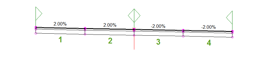
| 1 | 2 | 3 | 4 | |
|---|---|---|---|---|
| Use Superelevation | Left Lane Outside | Left Lane Inside | Right Lane Inside | Right Lane Outside |
| Slope Direction | Away from Crown | Away from Crown | Away from Crown | Away from Crown |
| Potential Pivot | Yes | Yes | Yes | Yes |
| Outside Point Code | Edge of Pavement (EC) | None | None | Edge of Pavement (EC) |
To build a single crowned carriageway assembly with axis of rotation pivot points
To build a single crowned carriageway assembly with axis of rotation pivot points, the parameters in the following table must be set as shown for each corresponding LaneSuperelevationAOR subassembly. The other lane subassembly parameters do not affect the axis of rotation pivot points.

| 1 | 2 | |
|---|---|---|
| Use Superelevation | Left Lane Outside | Right Lane Outside |
| Slope Direction | Away from Crown | Away from Crown |
| Potential Pivot | Yes | Yes |
To build a dual planar carriageway assembly with axis of rotation pivot points
To build a dual planar carriageway assembly with axis of rotation pivot points, the parameters in the following table must be set as shown for each corresponding LaneSuperelevationAOR subassembly. The other lane subassembly parameters do not affect the axis of rotation pivot points.
For best results, compose each side of the assembly as a separate group. If the assembly is composed as a single group, the Central Reserve Edges pivot methods is ignored, and the central reserve treatment is determined by the manner in which the assembly is built.
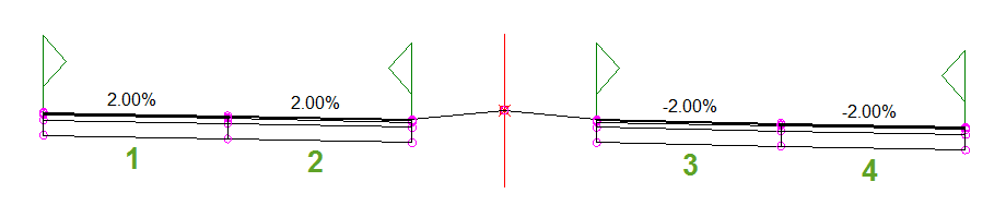
| 1 | 2 | 3 | 4 | |
|---|---|---|---|---|
| Use Superelevation | Left Lane Outside | Left Lane Inside | Right Lane Inside | Right Lane Outside |
| Slope Direction | Away from Crown | Away from Crown | Away from Crown | Away from Crown |
| Potential Pivot | Yes | Yes | Yes | Yes |
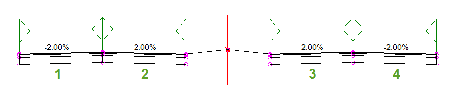
To build a dual crowned carriageway assembly built from crown
A dual crowned carriageway assembly with axis of rotation pivot points may be built with the inside lane crossfall direction either towards the crown or away from the crown. In this case, the inside lane crossfall direction is going away from the crown.
For best results, compose each side of the assembly as a separate group. If the assembly is composed as a single group, the Centers and Central Reserve Edges pivot method is ignored, and the central reserve treatment is determined by the manner in which the assembly is built.
The parameters in the following table must be set as shown for each corresponding LaneSuperelevationAOR subassembly. The other lane subassembly parameters do not affect the axis of rotation pivot points.
| 1 | 2 | 3 | 4 | |
|---|---|---|---|---|
| Use Superelevation | Left Lane Outside | Left Lane Inside | Right Lane Inside | Right Lane Outside |
| Slope Direction | Away from Crown | Away from Crown | Away from Crown | Away from Crown |
| Potential Pivot | Yes | Yes | Yes | Yes |
| Inside Point Code | Crown | Crown | Crown | Crown |
| Outside Point Code | Edge of Pavement (EC) | Edge of Pavement (EC) | Edge of Pavement (EC) | Edge of Pavement (EC) |
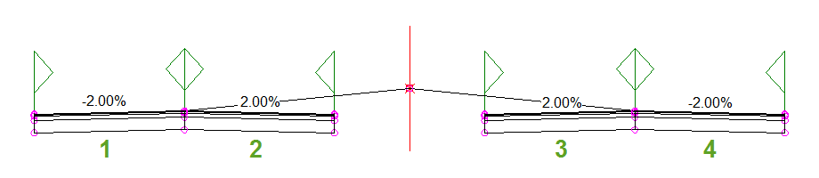
To build a dual crowned carriageway assembly built towards crown
A dual crowned carriageway assembly with axis of rotation pivot points may be built with the inside lane crossfall direction either towards the crown or away from the crown. In this case, the inside lane crossfall direction is going towards the crown.
For best results, compose each side of the assembly as a separate group. If the assembly is composed as a single group, the Centers and Central Reserve Edges pivot method is ignored, and the central reserve treatment is determined by the manner in which the assembly is built.
The parameters in the following table must be set as shown for each corresponding LaneSuperelevationAOR subassembly. The other lane subassembly parameters do not affect the axis of rotation pivot points.
| 1 | 2 | 3 | 4 | |
|---|---|---|---|---|
| Use Superelevation | Left Lane Outside | Left Lane Inside | Right Lane Inside | Right Lane Outside |
| Slope Direction | Away from Crown | Towards Crown | Towards Crown | Away from Crown |
| Potential Pivot | Yes | Yes | Yes | Yes |
| Inside Point Code | Crown | Edge of Pavement (EC) | Edge of Pavement (EC) | Crown |
| Outside Point Code | Edge of Pavement (EC) | Crown | Crown | Edge of Pavement (EC) |