Use this dialog box to specify how incremental vertexes are added along the 3D polylines or feature lines when generating rail lines.
Horizontal Alignment
Specifies how incremental vertexes are added along the rail lines in relation to the parent rail alignment.
- Along Straights
- Specifies the insertion frequency for vertexes along the straight portions of a rail line. Enter a value or click
 and select a distance in the drawing.
 - Along Curves
- Specifies how the frequency for inserting vertexes along curves is determined.
- By Curvature: Horizontal baseline curves are tessellated using the Mid-Ordinate Distance To Define Curvature value. Stations are created along the tessellated curve at each point where the tessellation touches the curve, as shown in the following illustration:
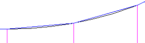
- At An Increment: Stations are placed along the curve at the value specified in the Curve Increment field.
- Both: Uses both the By Curvature option and the At An Increment option.
- By Curvature: Horizontal baseline curves are tessellated using the Mid-Ordinate Distance To Define Curvature value. Stations are created along the tessellated curve at each point where the tessellation touches the curve, as shown in the following illustration:
- Curve Increment
- Specifies the insertion frequency for vertexes along curves. The Along Curves setting must be set as At Increment or Both to change this setting. Enter a value or click and select a distance in the drawing.
- Mid-Ordinate Distance to Define Curvature
- Specifies the mid-ordinate distance for the rail line segments along curves. Enter a value or click and select a distance in the drawing.
- Along Transitions
-
Specifies the insertion frequency along the spiral portion of an alignment. Like curves, spirals are tessellated, and stations are created along the tessellated curve at each point where the tessellation touches the spiral. Enter a value or click
and select a distance in the drawing.
Note: This setting is not used when a feature line is specified for the horizontal baseline. - At Horizontal Geometry Points
- Specifies whether the vertexes should be inserted at horizontal baseline geometry points where the horizontal baseline geometry changes (such as the start of a curve).
- At Cant Critical Points
- Specifies vertexes on the rail line that correspond to the cant critical points on the parent alignment.
- At Mid of Curve
- Specifies vertexes on the rail line that correspond to the mid-curve points on the parent alignment.
- At Sample Line Stations
- Creates vertexes on the rail line that correspond to existing sample lines along the parent alignment. Click in the Value field and specify the sample line group to use.
Vertical Alignment
Specifies how incremental vertexes are added along the rail lines in relation to the profile of the parent rail alignment.
- Along Vertical Curves
- Specifies the insertion frequency of vertexes along curve portions of the profile geometry. Enter a value or click and select a distance in the drawing.
- At Vertical Geometry Points
- Specifies whether the vertexes should be inserted at vertical baseline geometry points where the vertical baseline geometry changes.
- At High/Low Points
- Specifies whether the vertexes should be inserted at the high and low points of the vertical baseline geometry.
Options for Adding and Deleting Stations
Creates vertexes on the rail line that correspond to manually specified stations along the parent alignment. The list of stations is listed at the bottom of the dialog box. Click  to add a station. To delete stations, select them from the list and click
  .
.