Visual cues help you edit junction components quickly.
Many of the dialog boxes that allow you to create or edit junction object components have visual behavior built in to help you quickly identify the area of the junction object being edited.
For example, editing dialog boxes, such as the Junction Offset Parameters dialog box and the Junction Corner Radius Parameters dialog box, contain the following behaviors:
Object Highlighting in Drawing: When you select some items on a junction editing dialog box, the affected object is highlighted in the drawing. For example, when you select an offset on the Junction Offset Parameters dialog box, that offset alignment is highlighted in the drawing. This behavior is displayed in the following illustration.
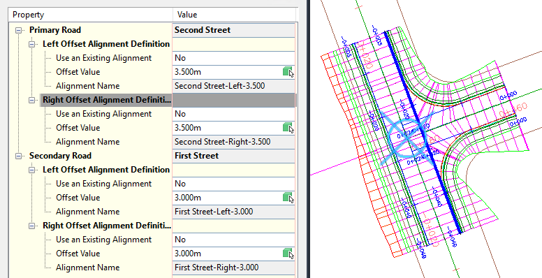
The right side offset alignment is selected in the Intersection Offset Parameters dialog box, shown on the left. In the drawing, that offset alignment is highlighted.
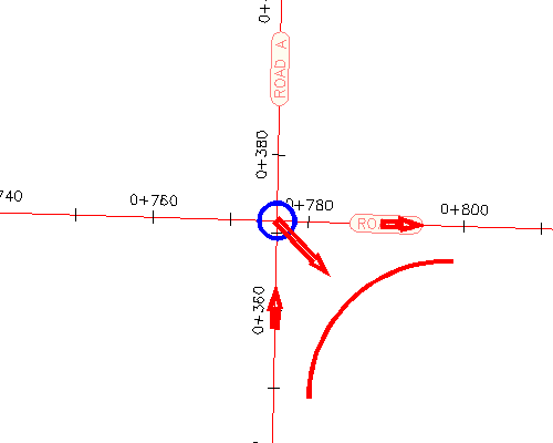
Similarly, if you are editing junction corner radius parameters using the Junction Corner Radius Parameters dialog box, each time you select a quadrant or corner radius in this dialog box, the selected quadrant or corner radius is highlighted in the drawing.
The following illustration shows temporary arrows along the alignments that indicate the direction of incoming and outgoing traffic. These arrows are displayed when you are specifying junction corner radius parameters.
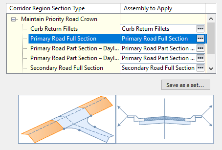
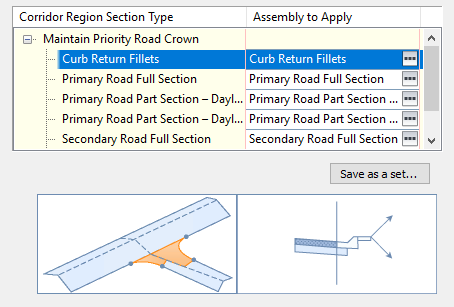
Conceptual Graphics on Dialog Boxes: Each time you select a property or item to edit on junction editing dialog boxes, the conceptual graphic is displayed at the bottom of the editing dialog box updates to indicate the location along the junction affected by the edit.
For example, when you select the “Primary Road Full Section” corridor region on the Intersection Corridor Regions dialog box, the following conceptual graphic is displayed, indicating the location of this region along the corridor.
Similarly, when you select the “Corner Radius Fillets” corridor region, the following conceptual graphic is displayed.
This behavior also exists on the Create Junction wizard dialog boxes.
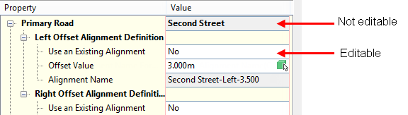
Shading of Non-editable Properties: In editing dialog boxes, properties that are not editable are displayed with a gray (shaded) background color. Properties that are editable are displayed with a white (not shaded) background color.