Use this dialog box to map attributes in ArcGIS data to pipe and structure properties in Civil 3D.
This dialog box is displayed when you use the Autodesk ArcGIS Connector to bring in ArcGIS data as pipes and structures.
You can also open this dialog box from within the Prospector item view. Select the pipe network in Prospector to display the item view and then click  in the Schema Mapping field of the item view.
This dialog box will have a tab for each pipe or structure layer that you are bringing in to Civil 3D so you can define mapping parameters for each layer.
Specifying schema mapping values
You can set up schema mapping to associate attributes that have been defined in ArcGIS data to pipe and structure properties that are used in Civil 3D.
For example, if there is a field named Structure_Height in the dataset, you can map that to the Structure Height property in Civil 3D so that the height value assigned to the part is the same height value defined in ArcGIS.
 Save Property Mapping File
- Saves the current configuration to a file that you can re-use when bringing in other pipe network data from ArcGIS.
 Open Property Mapping File
- Opens an existing property mapping file so it can be applied to pipe network data.
- Civil Property Name
- Displays the Civil 3D properties to which you can map ArcGIS attributes.
Items with an asterisk after their names are required.
- Civil Property Unit
- Displays the units that will be applied to the data in the drawing. The entries in these fields use the units specified for the current drawing (inches/feet or millimetres/metres) and cannot be changed.
- Source Property Name
- Specifies the attribute that will be mapped to the Civil 3D property. Click in the field to display a drop-down list of available attributes to choose from.
- Default Value
- Specifies a default value that will be used if a Source Property Name cannot be found in the ArcGIS data.
- Source Unit
- Specifies the source unit of the data.
- Value Mapping
- Opens the Value Mapping dialog box where you can specify Source Property Name values that correspond to Civil 3D properties.
The following example shows how to use the Value Mapping dialog box to map the source values for a "Structure_type" attribute so they are brought into Civil 3D as Junction structures.
The available properties in Civil 3D for the Part Type are Inlet-Plug Socket Structure and Junction.
If you want to bring in manholes, inlets and outfalls as Junction part types, you can set up the Value Mapping for the Part Type. For example, if attribute values Manhole, Inlet and Outfall were specified in the ArcGIS data to indicate the structure type, you can enter those values in the Value Mapping dialog box.
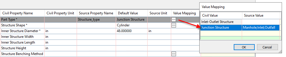
You can include multiple values by separating them with a semicolon. For example, Manhole;Inlet;Outfall. Entries are not case-sensitive.
Note: In the example above, all of these structures will be created in the drawing as generic Junction structures (with a Structure Type of <none>). You can manually set the Structure Type using the Structure Properties dialog box or you can use the Map Drainage Structure Parameters command to assign the Structure Type and other properties.