Use the Alignment Layout Tools to add complex curve groups to your alignment. Complex curve groups consist of multiple curves and transitions and are available in compound and reverse solutions.
Complex free curve groups are defined by the radius of each curve and the length or A value of each transition. Additionally, a second parameter must be specified for either of the two curves.
To add a free transition-curve-transition-curve transition between two straights
Add a free transition-curve-transition-curve-transition group between two straights.
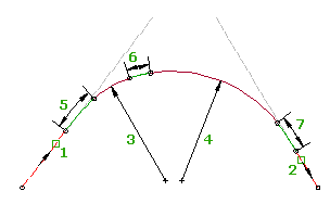
When the attachment straights (1, 2) are edited, the curve radii (3, 4) and transition lengths (5, 6, 7) do not change. The attachment points and the curve lengths adjust to accommodate edits to the attachment straights. The length of any of the transitions can be zero.

The compound Transition-Curve-Transition-Curve-Transition (TCTCT) group is placed between two straights. This group is similar to the transition-curve-transition (TCT) group, but it has a second curve and transition at the end of the group.
The TCTCT group accepts zero as a transition length, which allows you to create a multiple curve group with or without transitions. Any of the transitions in this group can have a zero length. A transition with zero length is effectively omitted from the group. The following combinations are possible by specifying zero as the transition length: TCTCT, TCTC, CTCT, CTC, TCCT, TCC, CCT, CC.
You cannot grip edit the TCTCT group, but you can edit the straights to which it is attached. The intersection point (IP) of the original straights is maintained, which causes the entire curve group to react to changes to either straight. You can edit the transition or curve parameters directly in either the Alignment Layout Parameters window or the Alignment Entities vista. If a transition in the group has zero length specified, the transition parameters are still displayed.
- Click the alignment. Click

 Find.
Find. - On the Alignment Layout Tools toolbar, click
 Free Compound Transition-Curve-Transition-Curve-Transition (Between Two Straights).
 - Select the straight (the First Element) from which you want to add the curve group.
- Select the straight (the Next Element) to which you want to add the curve group.
- Specify the length or A value of the first transition. Note: You can specify length by picking two points in the drawing. Zero is an acceptable length for any of the transitions in this curve group.
- Specify the radius of the first curve, or enter D to specify the degree of curvature. Note: To calculate the radius or degree of curvature using other known curve parameters, enter 'CCALC to open the Curve Calculator.
- Specify the length or A value of the second transition.
- Specify the radius of the second curve, or enter D to specify the degree of curvature.
- Specify the length or A value of the third transition.
- Enter a second parameter for one of the curves.
You can specify an extended straight length, start point on a straight, subtended angle, or pass-through point. Enter C to switch the curve for which you will enter the parameter.
To add a free reverse transition-curve-transition-transition-curve-transition between two straights
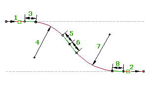
Add a free reverse transition-curve-transition-transition-curve-transition group between two straights that are nearly parallel.
This group consists of two successive transition-curve-transition groups in opposing directions. When the attachment straights (1, 2) are edited, the curve radii (4, 7) and transition lengths (3, 5, 6, 8) do not change. The attachment points and the curve lengths adjust to accommodate edits to the attachment straights.

You cannot grip edit the reverse TCTTCT group, but you can edit the straights to which it is attached. You can edit the transition or curve parameters directly in either the Alignment Layout Parameters window or the Alignment Entities vista.
- Click the alignment. Click

 Find.
Find. - On the Alignment Layout Tools toolbar, click
 Free Reverse Transition-Curve-Transition-Transition-Curve-Transition (Between Two Straights).
 - Select the straight (the First Element) from which you want to add the curve group.
- Select the straight (the Next Element) to which you want to add the curve group.
- Specify the length or A value of the first transition (the transition in). Note: You can specify length by picking two points in the drawing.
- Specify a radius for the first curve, or enter D to specify the degree of curvature. Note: To calculate the radius or degree of curvature using other known curve parameters, enter 'CCALC to open the Curve Calculator.
- Specify the length or A value of the second transition (the transition out).
- Specify the length or A value of the third transition (the transition in).
- Specify a radius for the second curve, or enter D to specify the degree of curvature.
- Specify the length or A value of the fourth transition (the transition out).
- Enter a second parameter for one of the curves.
You can specify a start point on a straight, subtended angle, or pass-through point. Enter C to switch the curve for which you will enter the parameter.