Use modifiers to create three-dimensional features of the model.
A modifier is a general term for any operation that affects features of the model. After creating profiles, you can use modifiers to extrude, add, or subtract features and to sweep a profile along a path. You can also use modifiers to create cut planes and transition features.
Part Builder provides six types of modifiers: extrusion, path, transition, cut plane, Boolean add, and Boolean subtract. The extrusion modifier is the most common type used in part modeling and is generally the base feature for a model. When you extrude a profile to create a feature, you specify how the feature will modify the shape by choosing one of four operations: midplane, plane, from-to, or blind.
Midplane Extrusion Modifier
A midplane extrusion uses a profile as the center of the extrusion and sweeps the profile an equal distance away from each side of the center.
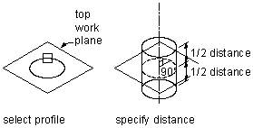
Applying a midplane extrusion modifier
Plane Extrusion Modifier
A plane extrusion sweeps a profile between the profile itself and a specified work plane. If the work plane is a reference work plane, the extrusion is updated when the work plane is moved.

Applying a plane extrusion modifier
From-To Extrusion Modifier
A from-to extrusion sweeps a profile between two work planes.
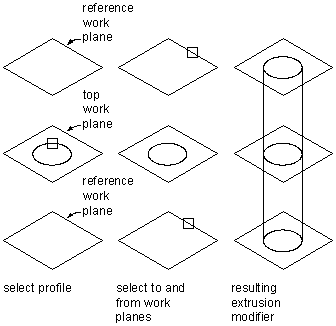
Applying a from-to extrusion modifier
Blind Extrusion Modifier
A blind extrusion sweeps a profile a specified distance along its normal, or perpendicular axis. You can flip the extrusion to sweep the profile in the opposite direction as the default normal.
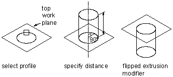
Applying a blind extrusion modifier
Path Modifier
A path modifier sweeps a profile along path geometry. It creates a 3D feature based on the start and end profile of a piece of geometry, such as a line or an arc. The start and end profiles can be different.
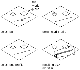
Applying a path modifier
You can also specify the number of segments to use to create a 3D feature.
Transition Modifier
A transition modifier creates a transition body between two profiles. A transition includes both a start and end profile, which cannot be in the same work plane. Point references are useful to ensure that the profiles align between work planes; however, the centers do not need to align.
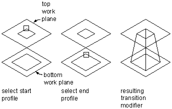
Applying a transition modifier
Cut Plane Modifier
A cut plane modifier cuts a feature into two parts, only one of which is kept. A cut plane modifier enables you to change the end of a feature to a slope, providing for the creation of more advanced features, such as an exhaust vent. You can modify the cut plane by dragging the normal, or perpendicular axis, of the modifier to create custom slopes. Cut planes are updated when the length of the modifier changes.

Applying a cut plane modifier
Boolean Add Modifier
A Boolean add modifier combines two features to create a single feature. This modifier assumes a basic concept of addition: that geometry inside other geometry, when added together, is removed. This modifier is helpful when creating models of parts that are placed in your drawing exactly as they were created in the model.
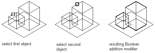
Applying a Boolean add modifier
Boolean Subtract Modifier
A Boolean subtract modifier subtracts one or more features from another to create a new feature. The Boolean subtract modifier uses a basic formula when creating the resulting feature: that the subtractor objects are removed from the base object. To see results in the model, the subtractor features must intersect with the base feature. When no intersection of features exists, the subtractor features are removed from the base feature with no visible change in the model.
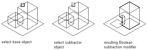
Applying a Boolean subtract modifier