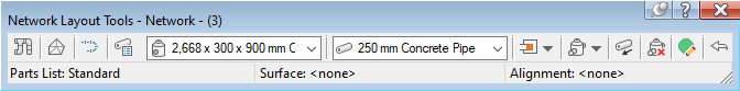
Use this toolbar to create or edit a pipe network.
The names of the parts list, surface, and alignment referenced in the currently selected pipe network are displayed at the bottom of this toolbar.
-
 Pipe Network Properties
 -
Opens the Pipe Network Properties dialog box, where you can control defaults and properties of the pipe network, such as the referenced parts list, object references, label defaults, and more.
-
 Select Surface
 -
Opens the Select Surface dialog box, where you can specify the surface referenced by any new parts to be added to the network. When a surface is selected, it is used to determine depths and levels of pipe network parts, based on rules for the part. If there are no surfaces in the drawing, this button is not available. Changes made to this selection will not affect parts already created in the pipe network.
-
 Select Alignment
 -
Opens the Select Alignment dialog box, where you can specify the alignment referenced by any new parts to be added to the network. If there are no alignments in the drawing, this button is not available. Changes made to this selection will not affect parts already created in the pipe network. The alignment provides chainage offset values for the pipe network parts, including the default alignment for labels.
-
 Parts List
 -
Opens the Select Parts List dialog box, where you can specify the parts list referenced by the current pipe network. The parts list controls the set of pipes and structures that are available to add in the current pipe network.
- Structure List
-
Specifies the type of structure currently selected for insertion into this pipe network.
- Pipe List
-
Specifies the type of pipe currently selected for insertion into this pipe network.
- Connection Point Options
-
Specifies the type of connection points to use when laying out pipe networks.
Note: To use the Default Connection Point and Closest Connection Point options, the structures must have connection points defined for them. See Pipe Network Content with Connection Points and Grips for information about parts which have connection points defined for them. You can also add connection points to custom parts by using the Infrastructure Parts Shape Utilities tools in Autodesk Inventor. For more information, see To add reference points. Structure Insertion Point: This option places the structure based on its insertion point and the structure insertion point is used as the connection point. This option replicates the existing behaviour in Autodesk Civil 3D 2019 and earlier.
Note: When this is the only option available for selection in the list and the other options are greyed out, it means that the structure you selected to insert doesn't have connection points defined on it.
Structure Insertion Point: This option places the structure based on its insertion point and the structure insertion point is used as the connection point. This option replicates the existing behaviour in Autodesk Civil 3D 2019 and earlier.
Note: When this is the only option available for selection in the list and the other options are greyed out, it means that the structure you selected to insert doesn't have connection points defined on it. Default Connection Point: This option places the structure based on the default connection point (the first connection point that is defined for a structure) and the default connection point is used as the connection point.
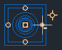
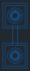
 Closest Connection Point: This option places the structure based on its insertion point and the closest connection point is used as the connection point. After you insert a structure, when you move your cursor over the structure, you can see the available connection points, shown as circles in the following illustration.
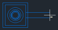
When you move the cursor away from the structure, a temporary graphic representing the pipe is drawn from the connection point on the structure that is closest to the cursor.
As you move your cursor around the structure, the pipe graphic is drawn from the next closest connection point.
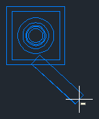
When you select the point for the second structure, the structure is placed in the drawing and the end of the pipe is connected to the connection point on the second structure that is closest to the first structure.
-
 Drawing Commands
 -
This drop-down button lets you specify whether to insert both pipes and structures, only pipes, or only structures.
When Pipes And Structures mode is selected, a structure is inserted at the first selection point, followed by a pipe. Subsequent selection points continue to insert structures connected to pipes.
 When Pipes Only mode is selected, you are prompted to select the start and end points for each pipe you insert. You can only insert pipes in this mode.
 When Structures Only mode is selected, you are prompted to select the insertion points for each structure you insert. You can only insert structures in this mode.
Note: The initial default command is Pipes and Structures. The initial prompt is Specify the structure insertion point: When reopening the toolbar, the default command is the last command that was used.
When Structures Only mode is selected, you are prompted to select the insertion points for each structure you insert. You can only insert structures in this mode.
Note: The initial default command is Pipes and Structures. The initial prompt is Specify the structure insertion point: When reopening the toolbar, the default command is the last command that was used. -
 Toggle Upslope/Downslope
 -
Specifies whether the gradient of the pipe network is upstream or downstream. This button acts as a toggle. When
is displayed, the pipe network gradient attribute is set to downgradient. When is  displayed the gradient attribute is set to upgradient. This also ensures that pipe rules are processed correctly.
-
 Delete Pipe Network Object
 -
Deletes the specified pipe network part from the drawing.
-
 Pipe Network Vistas
 -
Opens the Panorama window. Lets you display and edit the pipe network data in vistas. There is a vista for pipe object data and a vista for structure object data.
-
 Undo
Undo -
Reverses the last action.