You can create a pipe network using the Network Layout Tools.
To automatically reference chainage and level data for the pipe network, you can associate the pipe network with an alignment and a surface.
![]() Tutorial Exercise: Creating a Pipe Network
Tutorial Exercise: Creating a Pipe Network
- Click
 Find , or in the Prospector tree, expand the Pipe Networks collection, then right-click the Networks collection, and click Create Pipe Network By Layout.
- In the Create Network By Layout dialog box, in the Network Name field, enter a name for the pipe network.
To name the pipe network, select a default name from the naming template, or enter a new name.
- In the Network Description field, enter an optional text description for this pipe network.
- In the Network Parts List field, select a parts list or accept the default parts list for this pipe network.
- To view or change the default layers that will be assigned to various pipe network parts as they are created, click Layers to open the Pipe Network Layers dialog box.
- To reference a surface and/or an alignment, select the item from the list, or click to select a surface and/or alignment in the drawing.
- Optionally, you may select label styles for pipes and structures added to the pipe network. When <none> is specified, no labels are added to the items, but you can add labels later if desired.
- Click OK in the Create Network By Layout dialog box. The Network Layout Tools toolbar is displayed, and the pipe network name is displayed in the Pipe Networks collection on the Prospector tab.
- On the Network Layout Tools toolbar, select the desired parts (pipes and structures) in the Pipe List and Structure List. For example, select 48-inch Concentric Gully for a structure, and 12-inch Concrete Pipe 1 US Imperial for a pipe.
- Select the connection point type by clicking the Down Arrow button next to
 and selecting one of the following options:
Note: To use the Default Connection Point and Closest Connection Point options, the structures must have connection points defined for them. See Pipe Network Content with Connection Points and Grips for information about parts which have connection points defined for them. You can also add connection points to custom parts by using the Infrastructure Parts Shape Utilities tools in Autodesk Inventor. For more information, see To add reference points.
and selecting one of the following options:
Note: To use the Default Connection Point and Closest Connection Point options, the structures must have connection points defined for them. See Pipe Network Content with Connection Points and Grips for information about parts which have connection points defined for them. You can also add connection points to custom parts by using the Infrastructure Parts Shape Utilities tools in Autodesk Inventor. For more information, see To add reference points.-
Structure Insertion Point: This option places the structure based on its insertion point and the structure insertion point is used as the connection point. This option replicates the existing behaviour in Autodesk Civil 3D 2019 and earlier.
Note: When this is the only option available for selection in the list and the other options are greyed out, it means that the structure you selected to insert doesn't have connection points defined on it.
 Default Connection Point: This option places the structure based on the default connection point (the first connection point that is defined for a structure) and the default connection point is used as the connection point.
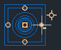
 Closest Connection Point: This option places the structure based on its insertion point and the closest connection point is used as the connection point. After you insert a structure, when you move your cursor over the structure, you can see the available connection points, shown as circles in the following illustration.
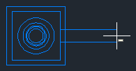
When you move the cursor away from the structure, a temporary graphic representing the pipe is drawn from the connection point on the structure that is closest to the cursor.
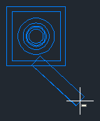
As you move your cursor around the structure, the pipe graphic is drawn from the next closest connection point.
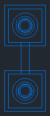
When you select the point for the second structure, the structure is placed in the drawing and the end of the pipe is connected to the connection point on the second structure that is closest to the first structure.
- Select the types of pipe network objects you want to insert by clicking the Down Arrow button next to
 Draw Pipes And Structures and selecting one of the following options:
- Pipes and Structures. Inserts pipes and structures during the same command operation. This is the default command when creating a new pipe network.
 Pipes Only. Inserts just one or more pipes (without inserting structures) into the pipe network.
 Structures Only. Inserts just one or more structures into the pipe network, without inserting any pipes.
Pipes and Structures is the default active layout command. The initial prompt (by default) upon entering the layout command is Specify the structure insertion point:
Upon reopening the layout toolbar, the default command is the last command that was used.
- Click the Toggle Upgradient/Downgradient button to set the direction of the pipe networks part(s) to either a positive gradient value or direction (upgradient) or a negative gradient value or direction (downgradient). This button acts as a toggle. Downgradient is the default. When the downgradient
 icon is displayed, each new pipe that is inserted will gradient downstream from the previous part. When the upgradient
  icon is displayed, each new pipe inserted will gradient upstream from the previous part.
- Begin drawing the pipe network by specifying the insertion point for the first part (pipe or structure) of the pipe network.
Note: If you are in Draw Pipes And Structures mode, the first click defines the first structure insertion point, as well as the starting point of the first pipe object. The second click specifies the end of the first pipe object, and inserts a new structure object connected to that pipe. Subsequent clicks specify insertion points for subsequent pipes and structures until you end the command by pressing Enter. If you are in Draw Pipes Only mode, each click specifies the insertion point for a pipe end (a pipe start point or end point). If you are in Draw Structures Only mode, each click specifies the insertion point for a structure.
- Specify the next insertion point in the drawing.
- When you finish drawing the pipe network, press Enter to end the command.
After you create a pipe network, you may want to refine parts of it. For example, you may want to add a new pipe or structure, remove parts, move parts, or add labels.