Differences in station values in bridge labels and profile view labels
Where there is a slope in the InfraWorks bridge road profile, the stations and elevations labelled on the bridge projection in Civil 3D may be different than the values shown in a profile view label that is added to the same location.
For example, for a bridge pier, the station in the InfraWorks model is determined perpendicular to the road profile (shown as location 1 in the illustration below). The value at location 1 will be used in Civil 3D as the station value for the bridge label.
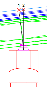
However, in Civil 3D profile view labels, the station is calculated straight up (shown as location 2 in the illustration above) and may not be perpendicular to the road profile where there is a slope in the InfraWorks model. If you add a profile view label at the same location as the pier label, the value at location 2 will be used as the station value in a profile view label and it may not match the station in the bridge projection label.
- The steeper the slope is, the greater the difference will be between location 1 and location 2.
- The longer the road is, the greater the difference will be between location 1 and location 2.
- All the top road elevation values that are listed in bridge labels for decks and piers are calculated using perpendicular stationing (location 1).
Bridge deck projection length
When the base alignment for the corridor is curved or composed of straights with angles between them, the projection of the bridge deck may be longer or shorter than the projection of the girders for the deck. The greater the curve or the sharper the angles are, the greater the difference will be between the deck and the girder projections.
This is because the girders may be comprised of several segments and each segment can be drawn at a different angle to more closely follow the alignment, whereas the deck (depending on the bridge complexity) may be a single object which does not have segments that can be drawn at different angles.
Bridge projection in multiple profile views
When you are projecting a bridge to multiple profile views, certain bridge components may extend beyond the range of stationing in a profile view.
- For a simple bridge, a projection of the bridge deck will be added to the profile view that its centre point belongs to and cannot be split into multiple profile views. This may result in portions of the deck extending beyond the range of the stationing for a profile view and the girders for the deck may be displayed in another profile view.
- The bridge deck of a more complex bridge may be able to be projected to multiple profile views. However, when such a bridge is projected to multiple profile views, a portion of the deck and its associated girders may extend beyond the range of the stationing for a profile view.
Profile view style in split profile views
Split profile views will ignore the scale settings in the parent profile view style and will apply the scale settings in the style specified for the split profile view.
You can specify whether a profile view is split and specify the style for each view, on the Elevations tab of the Profile View Properties dialog box.
Selecting individual bridge components
If you want to select individual girders in a girder group or generic objects that are part of tunnels, you can set the PICKSTYLE system variable to 0. When the PICKSTYLE system variable is set to its default setting of 1, selecting a girder will select the entire girder group and selecting a tunnel will also select its associated generic objects.