This section provides descriptions for some terms that are commonly used when referring to pipe network parts.
Structure Terms
- Cover. The top level of a manhole or gully (junction) structure.
- Frame. The support for the cover on a manhole or grate for a gully. The top level of the frame, cover, and grate typically coincides with the insert (cover) level.
- Manhole cover. The top access cover of a manhole, used for servicing or inspecting the manhole. Covers are typically circular in shape, but they can also be triangular, so that they do not fall into the manhole when removed. The cover sits in the frame and is usually constructed of cast iron.
- Grate. The top opening of a gully that typically contains numerous openings to allow surface water entry into the structure. The grate sits in the frame and is usually constructed of cast iron. Grates can be various shapes but are typically circular or square.
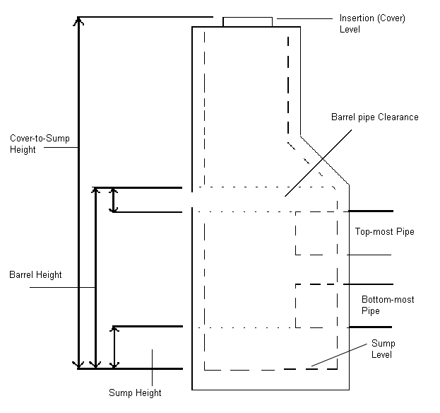
- Sump and sump depth. Sump refers to the bottom area or chamber on the inside of a junction structure, such as a gully. The sump area is sometimes used as a reservoir to catch debris. Sump depth refers to the distance from the bottom of the inside of the structure to the lowest invert of all pipes connected to it. The sump depth for a particular type of structure can vary according to design requirements. Manholes typically have no sump depth.
The following illustration shows the locations of components on a typical junction structure.

Pipe Terms
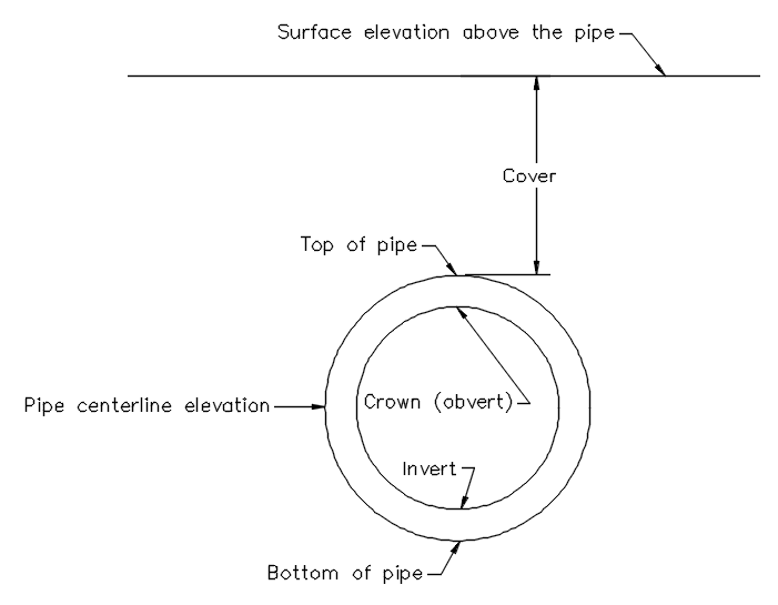
- Invert. The level of the inside bottom of a pipe. Also referred to as flowline.
- Crown or Obvert. The level of the inside top of a pipe.
- Pipe centreline level. The level of the centreline of a pipe.
- Cover or Level. Refers to the depth of the material above the topmost outer part of a pipe.
- Gradient. When gradient is used to refer to the gradient of a pipe, it is a measure of steepness. For pipes, the gradient is defined by rise (or fall) over run, where rise is the difference in level along a run of pipe length, measured horizontally. Gradient is typically represented in percent. For example, a slope of pipe at 2% means that for every 100 feet of horizontal length of pipe, the pipe falls 2 feet. In Autodesk Civil 3D, the slope can be represented in a variety of ways in dialog boxes and in labels in the drawing. A positive pipe slope indicates the pipe is sloped downwards in the direction of flow. A negative pipe slope is an adverse pipe slope indicating the pipe is sloped upwards in the direction of flow.
