Use the Layout tab to create a text component for a label style.
From the Create Component list ![]() , click
, click ![]() to create a new text component.
to create a new text component.
General
- Name
-
Specifies the name of the text component.
The default name, such as “Text.1,” is the component name with a numeric increment. If the text component exists in a parent label style, then the name cannot be edited.
- Visibility
-
Specifies whether the text component is visible in the label style.
- Used In
-
Specifies whether the component is displayed in Tag Mode, Label Mode, or both. Select a mode on the General tab in the Label Style Composer.
- Label Mode: Displays the text component when Display Mode is set to Label.
- Tag Mode: Displays the text component when Display Mode is set to Tag.
- Label and Tag Modes: Displays the text component regardless of the display mode setting.
Note: If a label style type does not support tables, then this control is not available. - Anchor Component
-
Specifies a reference object for positioning the text component. You can select <Feature> (which is the object being labeled) or another existing label component.
- Anchor Point
-
Specifies the location on the Anchor Component where the text component is attached.
- When <Feature> is the Anchor Component, Label Location is the only option available. This option places the anchor point at the location where the label is attached to the object.
- When the Anchor Component is another label component, you have a choice of anchor points depending on whether the anchor is a text, block, tick, line, or direction arrow component. For example, if the anchor is a text component, you can select from the points shown in the following illustration:
- Span Outside Segments
-
Specifies whether the label style component should span outside segments.
Note: This setting applies to plot line and curve label styles only.- True: Labels the outer boundary of plots, rather than the individual plot segments. For example, if four plots share an outer boundary, use this option to label the combined outer boundary.
- False: Labels individual plot segments.
Text
- Contents
-
Specifies the content of the text component. When a text component is first created, displays “Label Text” by default.
Click the Value column, and then click
 to open the Text Component Editor dialog box where you can create and edit the label content.
 - Text Height
-
Specifies the plotted height for text. Enter a positive value greater than zero.
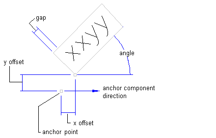
- Rotation Angle
-
Specifies the angle for the text component. Enter a positive or negative value, or
 click to select an angle in the drawing.
 The angle direction is always counterclockwise, and the zero (0) direction is determined by the anchor component type.
If the text component is anchored to a feature, then the zero direction is determined in relation to the following Orientation Reference settings on the General tab:
- Object: Calculates the zero angle by examining the object’s construction and then measuring the zero angle from the start to the end of the object. If the object is a curve, then the zero angle is straight to the curve.
- View: Sets the zero angle equal to the world coordinate system (WCS) base angle of East (horizontal, left to right).
- World Coordinate System: Sets the zero angle equal to the WCS base angle of East (horizontal, left to right).
If the text component is anchored to...
then the zero angle is measured...
another text component, a block component, tick component
along the component’s zero angle.
line component or vertex arrow component
from the start of the line to the end of the line.
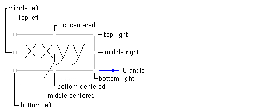
- Attachment
-
Specifies the location on the text component that is attached to the anchor point. Attachment points are calculated based on a rectangle that encompasses the text, the size of which is determined by including the Gap value specified in the Border category. The following illustration shows text attachment points:
- X Offset
-
Specifies the offset distance between the attachment point and the anchor point in the X direction (zero angle direction).
The X direction is determined by the object to which the text component is anchored. If the text component is anchored to the label insertion point, then the X direction is determined in relation to the following Orientation Reference settings on the General tab:
- Object: Calculates the X direction by examining the object’s construction and measuring the zero angle direction from the start to the end of the object. If the object is a curve, then the zero angle is located straight to the curve.
- View: The X direction is always horizontal, left to right, regardless of the User Coordinate System (UCS) or Dview twist direction.
- World Coordinate System: The X direction is the same as the User Coordinate System (UCS) base angle of East (horizontal, left to right).
- Y Offset
-
Specifies the offset distance between the attachment point and the anchor point in the Y direction, which is 90 degrees counterclockwise to the X direction.
- Allow Curved Text
-
Specifies whether text is drawn along a curve for curve label styles.
Border
- Visibility
-
Specifies whether the border is visible.
- Type
-
Specifies the shape of the border.
- Rectangular: Draws a rectangle around the text component.
- Rounded Rectangular: Draws a rectangle with round corners around the text component.
The radius used to create a rounded rectangle is calculated by adding the gap value and half the overall text height (including descending, subscript, and superscript characters).
- Gap
-
Specifies the distance between the border and text. The Gap is still applied if Border Visibility is set to False.
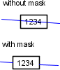
- Background Mask
-
Specifies whether a mask is applied to the component using the border shape and size.