Use work planes to define a part, position geometry, and define relationships between part features.
In Part Builder, a work plane is a modeling feature that defines the location of a plane in three-dimensional (3D) space. It is an infinite construction plane that can be placed at any orientation in space. It can be offset from an existing work plane, or it can reference 3D geometry. Using a work plane, you define the geometry, dimensions, constraints, and profiles that make up the part model. Work planes help you to place geometry that would otherwise be difficult to position. By constraining geometry to work planes, you can control their location. Work planes help you to define relationships between features and provide control when placing features.
A work plane is displayed as a rectangular two-dimensional (2D) object. The work plane display is only a visual representation of the infinite plane and cannot be moved or resized. However, you can control its visibility for ease of viewing the model. Offset and reference work planes are user-defined and provide the flexibility to be moved and redefined.
When you right-click on a work plane in the part browser, it is highlighted in the modeling area. You can change the view direction to match that of the selected work plane when adding geometry or dimensions by using the Set View option on the Work Plane context menu.
Part Builder provides three default work planes that intersect at the origin of the X, Y, and Z axes. The default work planes help you to get started with modeling a part. Generally, it is best to start your modeling in the top work plane, and add others as needed. You can add work planes at any time during the modeling process. Each work plane has its own internal coordinate system. Work planes can be created on any plane in the current user coordinate system (UCS) or in the World Coordinate System (WCS).
The following preset work planes can be added to a model from the Create Work Plane dialog box:
- Default
-
Creates the standard ZX, YZ, and XY work planes of the WCS.
- Custom
-
Creates a work plane that is not available by the preset work planes. The work plane has user-defined values for the X and Y direction and the origin of the plane in the current UCS.
- Offset
-
Creates a work plane that is offset by a specified distance from a selected source work plane. For more information, see Offset Work Planes below.
- Reference
-
Creates a work plane that is attached to the extents of a modifier feature. For more information, see Reference Work Planes below.
- Top
-
Creates a work plane that matches the standard Top 3D view.
- Bottom
-
Creates a work plane that matches the standard Bottom 3D view.
- Front
-
Creates a work plane that matches the standard Front 3D view.
- Back
-
Creates a work plane that matches the standard Back 3D view.
- Left
-
Creates a work plane that matches the standard Left 3D view.
- Right
-
Creates a work plane that matches the standard Right 3D view.
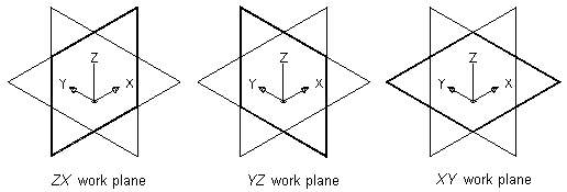
Viewing default work planes
Offset Work Planes
An offset work plane is a specified distance away from another work plane. This work plane can be offset from any existing work plane, including another offset or reference work plane. You define an offset work plane by selecting a source work plane and specifying a distance between the work planes. You can use offset work planes to maintain specified or calculated distances between features, such as profiles, geometry, or modifiers. You can also use offset work planes as construction guides for locating features that would otherwise be difficult to locate. For example, use an offset work plane to define the length of a transition.
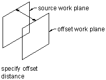
Creating an offset work plane
Reference Work Planes
A reference work plane is defined as a plane on the face of the extents of a modifier. Every modifier has an invisible extent, or boundary box, that defines the extents of the feature. You can create a work plane that references one of the planes of the extent. To define a reference work plane, you select a modifier and a source work plane that represents the plane direction you want to create. The extents, or boundary box, of the feature is detected, and two valid reference work planes are available for selection. If the modifier is moved or resized, the reference work plane is moved with it.
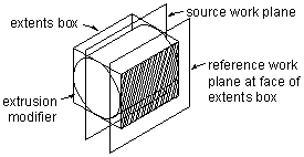
Creating a reference work plane