Use a section object to examine surfaces, corridor models and pipe networks along a sample line (across an alignment). In Autodesk Civil 3D, each section is an object.
Section sample lines
A section is an object that contains level data along a sample line. Each surface, corridor model, or pipe network that intersects the vertical plane defined by the sample line results in a section object.
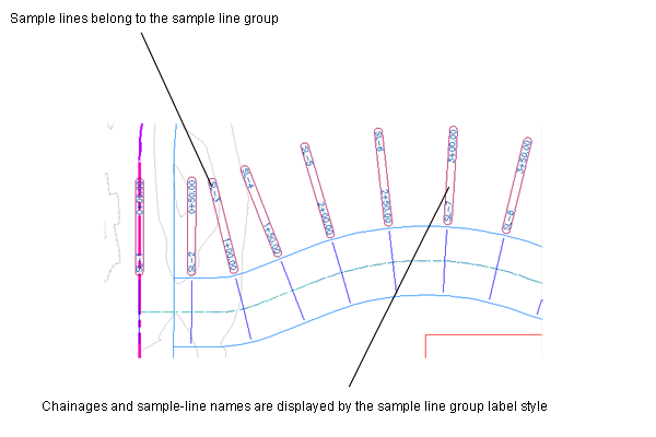
Sample lines cross an alignment to a specified distance to the left and right. Typically, sample lines are created at given chainages along a horizontal alignment.
When you create sample lines along an alignment, section objects are also created for a specified set of existing or proposed surfaces, corridor models, or pipe networks. Each sample line's default styles and sample objects are specified through a sample line group. Other sample objects may be added to the sample line group after the sample lines have been created. To plot the sections in the drawing, create individual section views or multiple section views.
Since sample line geometry controls where surfaces are sampled to create section objects, sample lines are the parent of the section object.
The following illustration shows sample lines.
Section views
To display sections in a drawing, you create section views. You create one or more section views along a sample line to graphically represent section objects at that location across an alignment. Thus, each section and section view are children of a sample line. Each sample line is associated with a sample line group, which is in turn associated with an alignment.
The following illustration shows a section view.
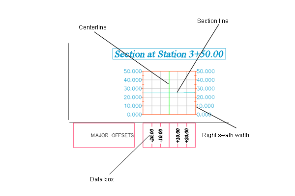
The section view object displays long section (both existing and finished ground/designed) along a sample line, at any given chainage along a horizontal alignment. A section view shows a section created from either a surface (Triangulation or corridor), a corridor (which is an assembly at a specified chainage), or a pipe network. Bands can also be displayed above or below the section view.
A section view, which is very similar to a profile view, is essentially a grid or graph with specific characteristics that are controlled by a section view style. Section views that relate to a sample line are stored in the Prospector tree in Toolspace under that sample line. Individual section views are accessible in Toolspace using the item view. If you delete a sample line in the drawing, section views under that sample line are also deleted.
A section view can include projections of other objects in the drawing that you want to see in relation to a section.
Section label sets
Sections, like alignments and profiles, support label sets. Label sets enable you to save and apply an unlimited number of different types of labels.
Surfaces in sections
When a surface is included in a section, it is defined by the following components:
- Vertices or gradient break points, where a gradient line ends and another line might begin
- Line segments, which detail the gradient of the surface between two gradient break points
For example, if a section is sampled from a Triangulation surface, then the gradient breaks are extracted at the point where the (vertical plane defined by) sample lines intersect with the Triangulation edges. Level between these two line segments is linearly interpolated and joined with a straight line (assuming that the sample line between these two points is also a straight line).
Corridors in sections
When a corridor is included in a section, the corridor is represented by the closed shapes and multiple layers that are formed by the corridor assemblies and subassemblies. For more information, see About Corridor Sections.
Pipe networks in sections
When a pipe network is included in a section, the section displays the network parts as specified in the pipe and structure style.