Interference checking lets you quickly identify pipe network parts that may be in conflict with each other.
This feature compares the actual 3D model of parts to check for interferences. You can run an interference check to identify pipe network parts that physically overlap, collide, or intersect in an inappropriate way, or that have violated predefined, proximity-based criteria.
For example, you may want to run an interference check on one or more pipe networks to see if any parts physically overlap or are too close to one another. You can select style-based visual markers to identify the interferences, or you can choose to display the interferences as true, three-dimensional representations. You may choose to leave the interference conditions as they are, or you may decide to resolve them by moving parts in the drawing.
When you run an interference check, you can choose a single pipe network or you can choose two pipe networks. When you run an interference check on a single pipe network, it checks for interferences on parts included in that network. When you choose to check two pipe networks, it checks for interferences between the two pipe networks.
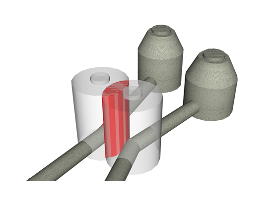
The following illustration shows two different pipe networks with structures that physically overlap. Running an interference check would quickly indicate that these parts interfere with one another.
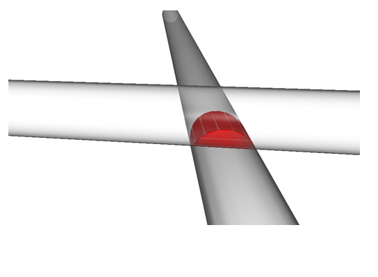
Another type of interference that can be detected is when two pipes intersect without a structure joining them, as shown in the following illustrations:
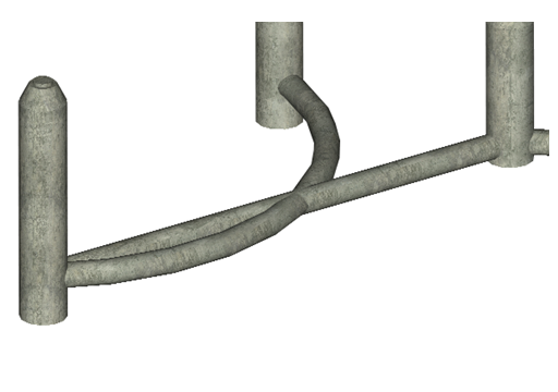
If desired, you can also perform a check for pipe network parts in their 3D representation that are too close to one another, according to predefined distance or scale factor criteria. In the following illustration, the two pipe networks shown are less than ten feet away from each other at the closest point, even though they do not physically collide:
You can run an interference check that identifies parts in their 3D representation that are less than a specified distance away from any part in the other network. The distance is checked in every direction surrounding each part.
When you run an interference check, an Interference Check object gets created and is displayed in the Prospector tree in the Pipe Networks  Interference Checks collection.
3D Proximity Checking Criteria
If you enable the 3D proximity checking option on an interference check, you can identify pipe network parts that are too close to one another in their 3D representation, according to a specified distance or a scale factor.
When you use proximity checking on a single pipe network, interferences are created for parts that are less than a specified distance from one another. When you use this feature to check two pipe networks, an interference is created for any parts from one network that are less than a specified distance or scale factor from any parts in the second network.
You can use the 3D proximity check feature to ensure that the distance between two different types of utility networks meets a certain requirement. For example, a sewer and water crossing typically requires that the water line be a minimum of 18 inches above the sewer line. Running an interference check with the Use Distance option set to 18 inches identifies any parts that were less than 18 inches away from the other pipe network.
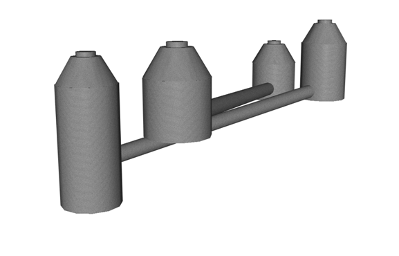
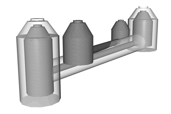
The following illustration shows how the distance and or the scale factor 3D proximity checking value is used to determine proximity interference violations. The darker shaded outlines represent the actual parts in the selected pipe network. The lighter shaded parts represent the area that is used to identify interferences.
Specifying a Distance
When you enter a specified distance to perform the proximity check, interferences are created for any pipe network part that is less than the specified distance away from any other part in the specified network(s), in any direction.
Specifying a Scale Factor
When the Use Scale Factor option is selected, you can enter a value that is used as a scale factor. When you enter a scale factor value, Autodesk Civil 3D calculates the limits of the part (the pipe or the structure) multiplied by the scale factor value that is specified. For example, if the pipe diameter is 600mm, and you specify a scale factor value of 2, Autodesk Civil 3D identifies any interferences within a distance of 1200mm (the pipe diameter, which is 600, multiplied by the scale factor value, which is two). When the interference check is run, any pipe network parts within that distance away from each other (in any direction) are marked as an interference.