To input traverse data
You can enter traverse data in the Traverse Editor by creating traverse sides. Side types can be Point, Line, Chord Arc, Radial Arc, or Side Shot. The first entry must be a start point (SP).
-
Click Home tab
 Create Ground Data panel
Traverse Menu
Traverse Editor
Find.
Create Ground Data panel
Traverse Menu
Traverse Editor
Find.
The Traverse Editor is displayed.
- If there is existing data in the Traverse Editor, click
 to create a new traverse.
- Before entering data, select one of the following options from the Draw drop-down list:
- Points and Lines: Creates COGO points and a polyline in the drawing as you enter traverse data.
- Points: Creates only COGO points in the drawing as you enter traverse data.
- Lines: Creates only a polyline in the drawing as you enter traverse data.
Note: The points that are created in the drawing will use the default point style and point label style specified in the point feature settings unless you enter description keys in the Description column of the Traverse Editor. Polyline objects are created on the current layer. The temporary graphics that are displayed in the drawing use the colour of the current layer. - If you will be entering arc data, ensure that Lines and Arcs is selected on the draw lines and arcs drop-down list so that the arc columns are displayed.
Tip: You can select the Lines option if you want to hide the Arc columns.
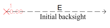
- Enter parameters in the first row of the Traverse Editor for the start point (SP).
Graphics for the initial backsight are displayed in the drawing.
- Specify subsequent Side types and then specify the requisite parameters.
Entering data for chord arcs
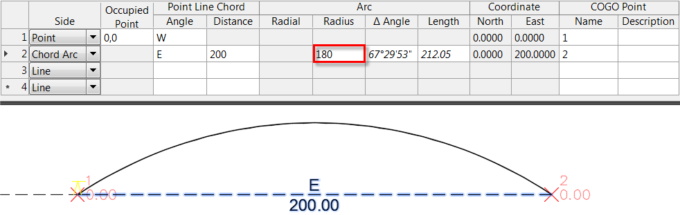
When entering data for chord arcs, you must specify an angle and distance and then you can specify either a radius, delta angle or length. The value you input directly for radius, delta angle or length is shown in regular font and calculated values are shown in italics. In the following illustration, 180 was entered for the radius and the delta angle 67 ° 29' 53" and length 212.05 are calculated.
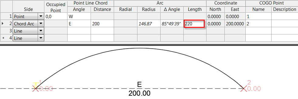
You can manually change the values shown in italics to recalculate the other values, which are then shown in italics. In the following illustration, 220 was entered for the length and the radius 146.87 and delta angle 85 ° 49' 39" were recalculated.
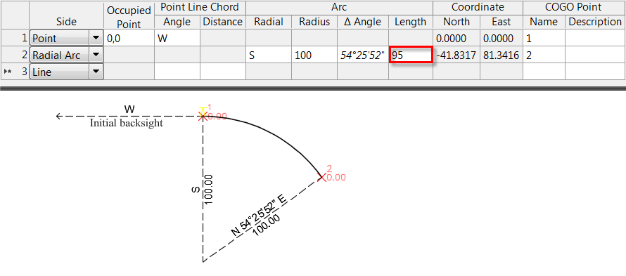
Entering data for radial arcs
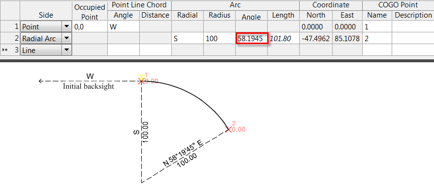
When entering data for radial arcs, you must specify a radial direction and a radius and either a delta angle or length. The value you input directly for delta angle or length is shown in regular font and calculated values are shown in italics.
Changing the radius or delta angle recalculates the length. Changing the length recalculates the delta angle.
In the following illustration, 58.1945 was entered for the delta angle and the length 101.80 is calculated.
In the following illustration, 95 was entered for the length and the delta angle 54 ° 25' 52" is calculated.
For more information about conventions for entering data, see the Traverse Editor reference topic.
Tip: You can right-click in the Traverse Editor to access a context menu with commands you can use to delete a row, to insert a row between existing rows and to reorder rows. - Click
 to save the traverse to a TRV2 file.
- To open the file in the Traverse Adjustment dialogue box, click Load balance Tool
 .
.
To create traverse data by selecting a polyline in the drawing
You can generate traverse data by selecting an existing polyline in the drawing.
-
Click Home tab
Create Ground Data panel
Traverse Menu
Traverse Editor
Find.
The Traverse Editor is displayed.
- Click
 and then select the polyline in the drawing.
The Traverse Editor is populated with the information from the polyline.
- Click to save the traverse to a TRV2 file.
- To open the file in the Traverse Adjustment dialogue box, click Load balance Tool
.