Use this dialog box to edit the levels and gradients for feature line, plot line, or survey figure segments. You cannot change the values of the chainages or segment lengths.
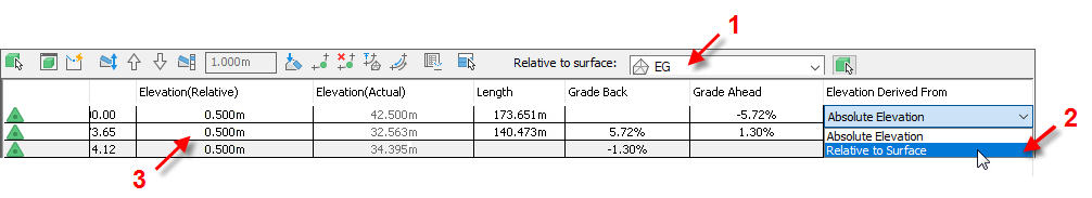
Use the Shift or Ctrl key to select multiple rows for editing.
Icons
-
 Select Line
 -
Selects a feature line, plot line, or survey figure for editing.
-
 Zoom To
 -
Zooms the drawing display to the selected intersection point (IP) or level point.
-
 Quick Profile
 -
Creates a quick profile of the feature line.
-
 Raise/Lower
 -
Adjusts the level of the points either upward or downward. Click the Raise/Lower and then enter the amount in the text box.
If no rows are selected, all rows are adjusted by the same amount. If rows are selected, the first selected point is adjusted to the specified level, then all the remaining selected rows are adjusted by the difference between the first point's previous level and its new level. For example, if the first point selected is at 3ft and you enter 10ft, the level of the first point is moved to be at 10ft and 7ft is added on to the other points that are selected.
-
 Raise Incrementally
 -
Adjusts the levels of all points upward by the increment value. If no rows are selected, the option adjusts all points, otherwise it adjusts the points only for the selected rows.
-
 Lower Incrementally
 -
Adjusts the levels of all points downward by the increment value. If no rows are selected, it adjusts all points, otherwise it adjusts the points for the selected rows.
-
 Set Increment
 -
Specifies the value to be used by the Raise and Lower commands. Enter the value.
-
 Flatten Levels
 -
Specifies that the levels of all selected rows are flattened to either the same level as the first row in the selection, or a constant gradient from the start level to the end level of the selection. Click to open the Flatten dialog box.
-
 Insert Level Point
 -
Inserts a level point between the start and end chainages of the footprint, creating an intermediate level point.
-
 Delete Level Point
 -
Deletes a level point between the start and end chainages of the footprint. You can delete only a single-row selection of intermediate level points.
-
 Levels From Surface
 -
Opens the Set Levels From Surface dialog box so you can set the feature line levels from a surface in the drawing. This option is disabled if the drawing has no surfaces.
- If the Relative Level to Surface check box is selected, the levels of all points are updated regardless of whether rows are selected in the Grading Level Editor.
Any feature line point that is off the surface keeps its existing level and it is set to be absolute.
- If the Relative Level to Surface check box is cleared and no rows are selected in the Grading Level Editor, the levels of all points are updated.
If rows are selected in the in the Grading Level Editor and the Relative Level to Surface check box is cleared, the update behaviour depends upon whether the Insert Intermediate Gradient Break Points check box is selected or cleared.
- If Insert Intermediate Gradient Break Points check box is also cleared, then just the selected rows are updated.
- If the Insert Intermediate Gradient Break Points check box is selected, the levels of all points are updated, regardless of whether rows are selected.
If the feature line is off the surface, a warning message is displayed. If some levels are updated, but one or more points are off the surface, a message is displayed indicating the number of points off the surface that could not be assigned levels. Any feature line point that is off the surface keeps its existing level.
- If the Relative Level to Surface check box is selected, the levels of all points are updated regardless of whether rows are selected in the Grading Level Editor.
-
 Reverse
 -
Changes the direction of feature lines. Updates the editor so that the order of points is reversed. This command affects the labeling and chaining of feature lines.
-
 Show Gradient Breaks Only
 -
Displays only the feature line start/end points and any gradient breaks in between. This option simplifies the editing process by allowing level edits to span multiple points. By default, the table displays all feature line points.
-
 Unselect All Rows
 -
Clears any selected rows so that the Raise, Lower and Flatten commands affect the entire length of the footprint.
- Relative To Surface
-
Specifies a surface to which the feature line levels will be relative.
Specifying a surface in this list displays the Level (Relative) column and the Level Derived From columns if they were not previously displayed. If you select <none>, those columns are hidden.
Note: Relative level options are also supported when editing plot lines in the Grading Level Editor, but not when editing survey figures or extracted feature lines that are dynamic to parent corridors or to parent alignments/profiles.If the feature line was not originally created relative to a surface, after you select a surface in this list, use the drop-down selection in the Level Derived From column to select Relative To Surface for the feature line points that will be relative to the surface. You can then also enter a level in the Level (Relative) column to offset the points above or below the surface.
Selecting a surface and setting points relative to the surface has the following effects, depending on how the feature line was initially created:
- If the feature line was initially created relative to a surface, selecting a different surface from the Relative To Surface list will update the Level (Actual) values. If values are specified in Level (Relative) column, they are preserved and applied to the surface levels to result in the actual levels.
For example, the following feature line was created 0.500m relative to surface EG.

If the surface is changed to First Street, the values in the Level (Relative) column are applied now to First Street surface levels to result in the new levels in the Level (Actual) column.

- If the feature line was initially created at a fixed level or gradient, after setting the feature line to be relative to a surface, the Level (Relative) column will display the difference between the Level (Actual) and the specified surface at that point. The value in the Level (Actual) is not changed.
For example, the following feature line was created with its first point at a fixed level of 10.000m and the next point at a gradient of 2.00%. It is not relative to a surface.

If it is changed to be relative to surface EG, the actual level stays the same and the Level (Relative) column shows the elevational difference between the feature line and the surface.
 Note: In this case, if you want to reset the actual levels to the surface levels, you can use the
Levels From Surface option described above.
Note: In this case, if you want to reset the actual levels to the surface levels, you can use the
Levels From Surface option described above.
For more information on this behaviour, see About Relative Feature Lines.
- If the feature line was initially created relative to a surface, selecting a different surface from the Relative To Surface list will update the Level (Actual) values. If values are specified in Level (Relative) column, they are preserved and applied to the surface levels to result in the actual levels.
Columns
- Symbol
-
- Green triangles
 mark the points that represent the major horizontal geometry points. For example, when you create a feature line, all vertices are shown as triangles. If you insert intersection points (IP), they are also shown as triangles.
- White triangles
 indicate split points, where two feature lines cross although neither has a geometry point at that location. You cannot directly edit the level of these points. For more information, see "Split points" below.
Note: The grey point icons also represent read-only objects, such as daylight lines and dynamically linked feature lines.
indicate split points, where two feature lines cross although neither has a geometry point at that location. You cannot directly edit the level of these points. For more information, see "Split points" below.
Note: The grey point icons also represent read-only objects, such as daylight lines and dynamically linked feature lines. - Circles
 mark the level change points. Insert a new level point by using the Insert Level Point icon in the Grading Level Editor.
Note: When a vertex is a shared point with another intersecting feature line, a small + symbol is displayed with the icon for that row.
- Green triangles
- Chainage
-
Identifies the point that starts the current segment.
- Level (Relative)
-
Specifies the positive or negative relative level of the point identified by the Chainage. This level is relative to the surface that is specified in the Relative To Surface drop-down list.
For example, if the relative level is 0.5 m, then the point is 0.5 m above the specified surface.
Note: If no surface is specified in the Relative To Surface drop-down list, then the Level (Relative) column is hidden. - Level (Actual)
-
Specifies the actual level of the point identified by the Chainage.
- Length
-
Displays the length of the current segment.
- Gradient Ahead
-
Specifies the end level of the current segment in the forward direction. Modifying this gradient will change the level of the segment. This is the level of the next Chainage point in the next row of the grid.
- Gradient Back
-
Specifies the gradient of the current segment from its end to start. Modifying this gradient will change the start level of the segment, which is the point at the beginning of the current row.
- Level Derived From
-
Specifies whether the level is absolute or is relative to the surface specified in the Relative To Surface drop-down list.
Note: Selecting a surface from the Relative To Surface list does not automatically make all the feature line points relative to that surface. You must also ensure that the Relative To Surface option in the Level Derived From list is selected for each point that you want to be relative. You can then also enter a level in the Level (Relative) column to offset the points above or below the surface.