Feature line elevations can be obtained from a surface and can also be relative to a surface, so if the surface is updated, the feature line is updated.
The update behaviour of relative feature lines is different depending on whether the feature line was set to be relative to a surface when it was created, or whether it was created at absolute elevations and then set to be relative.

|
 Watch Video: Use Relative Feature Lines to Model a Surface Watch Video: Use Relative Feature Lines to Model a Surface
Set feature line levels to be relative to a reference surface and add the relative feature lines to a different surface as breaklines. |
 00:03:56
 With Audio
Behaviour of feature lines created to be relative
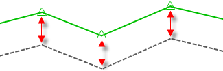
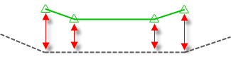
The following illustration shows a feature line in green drawn so that it follows the surface levels (shown in a dashed grey line) at a positive elevational offset. This feature line was created so that it is relative to the surface.
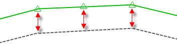
If the surface is edited, the feature line is updated automatically and maintains the elevational offsets, as shown in the following illustration.
Behaviour of feature lines created at fixed levels and then set to be relative
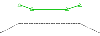
The following illustration shows a feature line that was drawn at fixed levels with no relationship to the surface. If the surface below it is edited, the feature line levels will not update.
The feature line is then set to be relative to the surface. This creates a relationship between the feature line and the surface but does not reset the feature line levels to follow the surface.
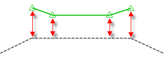
However, the relative elevational offsets between the feature line and the surface will now be maintained if the surface is edited, such as if the level is lowered, as shown in the following illustration.
Using relative feature lines as data in surface definitions
The following table contains information about using relative feature lines as data in surface definitions in Autodesk Civil 3D 2018 and the Autodesk Civil 3D 2018.1 Update.
| Autodesk Civil 3D 2018 | Autodesk Civil 3D 2018.1 |
|---|---|
|
In Autodesk Civil 3D 2018, if you want to use a relative feature line as breakline or boundary data in a surface, make the feature line relative before defining it as a breakline or a boundary. A non-relative feature line that is defined as data in a surface can not be made relative to any surface. |
In Autodesk Civil 3D 2018.1, a non-relative feature line that is defined as a breakline or a boundary in a surface can subsequently be made relative to a surface (other than a surface in which it is defined as data).
Note: In Autodesk Civil 3D 2018.1, a feature line cannot be made relative to a surface in which it is defined as breakline or boundary data.
|
|
In Autodesk Civil 3D 2018, if a relative feature line is defined as breakline or boundary data in a surface, its relative surface association cannot be changed. |
In Autodesk Civil 3D 2018.1, if a relative feature line is defined as breakline or boundary data in a surface, its relative surface association can be changed (to a surface other than one in which it is defined as data). |
|
In Autodesk Civil 3D 2018, avoid adding a relative feature line as a breakline or a boundary to the same surface to which it is relative. |
In Autodesk Civil 3D 2018.1, a relative feature line cannot be added as a breakline or a boundary to the same surface to which it is relative. |
In either Autodesk Civil 3D 2018 or Autodesk Civil 3D 2018.1, issues can occur as a result of circular dependencies if feature lines that are relative to different surfaces are then added as breaklines or boundaries to each other's surface definitions. For example, if Feature Line 1 is relative to Surface 1 and Feature Line 2 is relative to Surface 2, issues can occur if Feature Line 1 is defined as data in Surface 2 and Feature Line 2 is defined as data in Surface 1. In such a situation, rebuilding each of the surfaces will cause the other one to become out of date.
Editing relative feature lines
Feature line editing commands are supported for relative feature lines.
When you open the Grading Level Editor for a feature line that is set to be relative to a surface, you will see the selected surface listed in the Grading Level Editor, and the editable feature line points will be shown as being relative to the surface.
You can specify relative level options by using the following features in the Grading Level Editor.
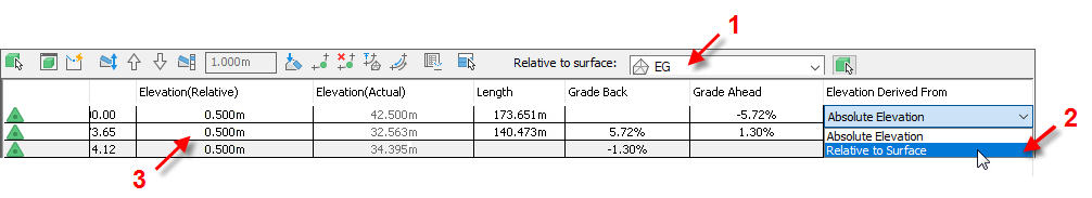
For a feature line that was not previously set to be relative to a surface, when you open the Grading Level Editor and then select a surface from the Relative to Surface list, the Level Derived From column is initially set to Absolute Level for all points and does not automatically change to Relative to Surface. Use the drop-down list to select Relative to Surface for the points that you want to be relative.
Updating level points on a relative feature line
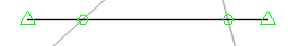
When you create a feature line and assign levels based on a surface, you can select the Insert Intermediate Gradient Break Points tick box. This creates level points along the feature line where the feature line crosses surface TIN lines. These points are shown as green circles in the following illustration.
If you edit or otherwise move a relative feature line, or if the surface it's relative to is updated, level points are not automatically added or removed on the feature line to match the surface TIN lines, as shown in the following illustration.
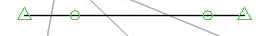
You can update the level points on the feature line by using the Insert Level Point and Delete Level Point editing options in the Grading Level Editor or on the Edit Levels panel of the Feature Line ribbon tab.