If a part family does not have the sizes you need, you can modify the part family sizes using the Part Builder feature.
To edit pipe network part family sizes
- Enter PartBuilder at the command line and press Enter.
- Select Pipe or Structure from the Part Catalog drop-down list.
- Using the catalog tree, locate and select the Part Family you want to edit. Note: Pipe and structure families are organized by type. For example, pipe families are organized into types such as circular pipes, egg-shaped pipes, and so on. Structure families are organized into inlet-outlet structures, junction structures with frames, and so on.
- Click the Modify Part Sizes button
 , or double-click the Part Family, to display the Part Family browser window.
 - If this is a Part Family that shipped with Autodesk Civil 3D, click the Save Part Family As button
 in the Part Family browser window toolbar
 - In the Save Part Family As dialog box, enter a new Part Name and Part Description and then click OK. This creates your own version of the selected Part Family you can edit.
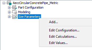
- In the Part Family browser window, right-click the Size Parameters node, and click Edit Values.
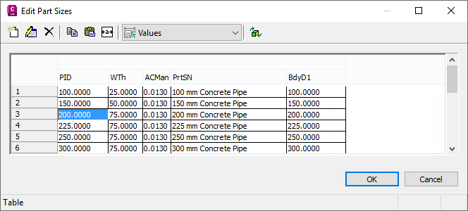
- In the Edit Part Sizes dialog box, find the parameter (property) value(s) you want to edit.
- Edit the values as described below:
Pipe values
- To change values for pipe sizes, select the row and size cell. Double-click to edit.
- To delete a size row, select the row and click the Delete button
 on the Edit Part Sizes dialog box.
 - To add a size row, select the closest size and click the New button
 on the Edit Part Sizes dialog box, and then edit the values in the new row.
Structure values
- To edit list values for structure sizes, select the cell and click the New button
 on the Edit Part Sizes dialog box.
- After you have completed editing sizes, click OK on the Edit Part Sizes dialog box.
- In the Part Family browser window toolbar, click the Save Part Family button
 .
. - When finished editing part sizes, close the Part Builder by clicking the close
 button in the upper right corner of the Part Family browser window.
 - You will be prompted to save the part family with the following dialog box. Click Yes at this prompt.
- Next, you may be prompted to save the part family drawing file with the following dialog box. Click No at this prompt.
The new part family and the new part sizes you create will be available through the Network Layout Tools toolbar.
To edit part sizes in the Concrete Pipe part family
This sample exercise walks you through how to edit the part sizes that are available in a part family.
- Enter PartBuilder at the command line and press Enter.
- Click the Part Catalog drop-down list and select Pipe.
- In the catalog tree, expand the Circular Pipes node, then select the Concrete Pipe part family.
- Double-click the Concrete Pipe part family or click the Modify Part Sizes button .
- Click the Save Part Family As button .
- In the Save Part Family As dialog box, enter a new Part Name and Part Description for this new part family and then click OK. This creates your own version of the selected Part Family you can edit.
- In the Part Family browser, right-click the Size Parameters node, and click Edit Values.
- In the Edit Part Sizes dialog box, click the Autosize Column Text button then find the Pipe Inner Diameter (PID) value and the Wall Thickness (WTh) values.
- Select any row in the table and click the New button on the Edit Part Sizes dialog box. The selected row is copied to the table.
- In the new table row, edit the PID and WTh values by double-clicking on them and typing in the new values.
- After you have completed editing sizes, click OK on the Edit Part Sizes dialog box.
- In the Part Family browser window toolbar, click the Save Part Family button .
- When finished editing part sizes, close the Part Builder by clicking the close button in the upper right corner of the Part Family browser window.
- You will be prompted to save the part family. Click Yes at this prompt.
- Next, you may be prompted to save the part family drawing file. Click No at this prompt.
The new part family will not be available when creating or editing a pipe network until you edit the parts list and add this new part family to your parts list.
Once you have added the new part family to your parts list, the new part family and the new part sizes you created will be available through the Network Layout Tools toolbar.