A subassembly is an Autodesk Civil 3D drawing object (AECCSubassembly) that defines the geometry of a component used in a corridor section.
Add subassembly objects to an assembly object to create a road cross section. Through tool palette and tool catalogs, Autodesk Civil 3D provides preconfigured subassemblies for components such as travel lanes, curbs, side slopes and ditches. These subassemblies are defined by a set of points, links, and optionally closed areas referred to as shapes.
Each subassembly has a defined cross-section, and some subassemblies automatically adapt to their location. For example, the slope of a road lane changes as superelevation is applied, and a side slope automatically creates either a cut or fill slope, depending on the relative level of the existing surface. The dimensions of a subassembly, such as the width of a lane or the height of a kerb are stored as properties.
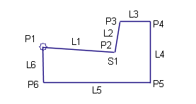
A subassembly definition references point, link, and shape codes. Points are the vertices of the subassembly, and they can be attachment points for adjacent assemblies. Links are the line segments or curves between the points. Shapes are two-dimensional polygons that represent the cross-sectional shape of the subassembly. The following figure shows a coding diagram for a Basic Kerb and Drainage Channel subassembly:
The subassemblies provided with Autodesk Civil 3D have built-in intelligent behavior. They can automatically adapt to conditions such as superelevation and cut or fill requirements. For example, a side slope subassembly has variable slopes that change automatically depending on the depth of cut along the corridor. In fill conditions exceeding a given depth, the shoulder automatically widens to include a guardrail or barrier.
After you determine the kinds of subassemblies to use, make sure they are available through an Autodesk Civil 3D tool palette or tool catalogs available through the Content Browser.
In addition to ready-to-use subassemblies, Autodesk Civil 3D also lets you create your own custom subassembly objects from polylines. In this case, you must also specify the subassembly behavior within an assembly and in the process of corridor creation. You can also design subassemblies using .NET language (see Autodesk Civil 3D Developer’s Guide) or the Subassembly Composer.
Layout and Modeling Modes
A subassembly that has not yet been applied to a corridor is considered to be in layout mode. After you create a corridor, all subassemblies included in the corridor model are considered to be in modeling mode.
Conditional Subassemblies
You can use a special type of subassembly called a conditional subassembly that automatically inserts other specified subassemblies when certain conditions are met.
For example, a conditional corridor assembly could contain two ConditionalCutOrFill subassemblies. The first ConditionalCutOrFill subassembly can be configured to apply a ditch subassembly when a cut condition exists. The second ConditionalCutOrFill subassembly can be configured to apply a guardrail, shoulder, and daylight to surface when a fill condition exists. Using conditional subassemblies enables you to reduce the number of corridor regions and assemblies that you have to maintain.
An assembly that contains one or more conditional subassemblies can be referred to as a conditional assembly.