Applies a highly customizable multi-color gradient that can be animated.
Gradient Ramp is similar to the Gradient map however any number of colors or maps may be specified and almost any parameter can be keyframed.
-

 Material Editor > Material/Map Browser > Maps > General > Gradient Ramp
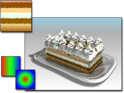
Gradient ramp used for the layers of the cake
When you replace an existing map with a gradient ramp map, choosing to Keep Old Map as Submap in the Replace Map dialog, the old map becomes assigned to the first flag as a texture.
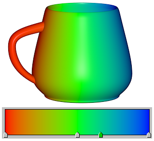
Gradient Ramp-mapped material with a colored gradient
Interface
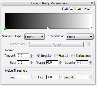
Gradient bar shows default gradient and interpolation types
- [gradient bar]
- Displays an editable representation of the gradient being created. The effect of the gradient moves from left (start point) to right (end point).
By default, three flags appear along the bottom edge of a red/green/blue gradient. Each flag controls a color (or map). The currently selected flag is green, and its RGB value and its position in the gradient (in the range 0 to 100) appear above the gradient bar. Each gradient can have any number of flags.
The gradient bar has the following features:
- Click anywhere along the bottom edge to create additional flags.
- Drag any flag to adjust the position of its color (or map) within the gradient. The start and end flags (Flag #1 at 0 and Flag #2 at 100) cannot be moved. However, other flags can occupy these positions and still be moved.
- More than one flag can occupy a given position. If two flags are at the same position, a slight edge appears between the colors. With three or more flags at the same position, the edge is a hard line.
- Right-click options for gradient bar
- Right-click in the gradient bar to display a menu with these options:
- Reset Resets the gradient bar to default values.
- Load Gradient Loads an existing gradient (DGR) file into the gradient bar.
- Save Gradient Saves your current gradient bar as a DGR file.
- Copy Copies the gradient.
- Paste Pastes a copied gradient into the current gradient.
- Load UV Map Loads a UV map to control the current gradient.
Loading a UV map turns off Flag Mode.
- Load Bitmap Loads a bitmap to control the current gradient.
Loading a bitmap turns off Flag Mode.
- Flag Mode Toggles flag display.
Turning on flags disables the map you might have loaded.
- Right-click options for flags
-
Right-click any flag to display a menu with the following options:
- Edit Properties Choose this option to display the Flag Properties dialog.
- Copy Copies the current flag values.
- Paste Pastes flag values to the current flag.
Note: You can paste to a Gradient Ramp other than the current map.
- Delete Deletes the flag.
- Gradient Type drop-down list
-
Chooses the type of gradient. The following Gradient types are available. These affect the entire gradient.
- 4 Corner An asymmetrical linear transition of colors.
- Box A box.
- Diagonal A linear diagonal transition of colors.
- Lighting Based on the light intensity value. No light=far left; brightest light=far right.
- Linear A smooth, linear transition of colors.
- Mapped Lets you assign a map to use as the gradient. Enables the Source Map controls for specifying the map and turning it on and off.
- Normal Based on the angle between the vector from the camera to the object and the surface normal vector at the sample point. The leftmost flag of the gradient is 0 degrees; the rightmost flag is 90 degrees.
- Pong A diagonal sweep that repeats in the middle.
- Radial A radial transition of colors.
- Spiral A smooth, circular transition of colors.
- Sweep A linear sweep transition of colors.
- Tartan A plaid.
- Interpolation drop-down list
-
Chooses the type of interpolation. The following Interpolation types are available. These affect the entire gradient.
Note: Gradients are ordered from left to right. The “next” flag is to the right of the current flag; the “previous” flag is to the left.- Custom Sets an individual interpolation type for each flag. Right-click the flag to display the Flag Properties dialog and set the interpolation.
- Ease In Weighted more toward the next flag than the current flag.
- Ease In Out Weighted more toward the current flag than the next flag.
- Ease Out Weighted more toward the previous flag than the next flag.
- Linear (The default.) Constant from one flag to the next.
- Solid No interpolation. Transitions are a sharp line.
- Source Map
- Click to assign a map to a mapped gradient. The checkbox turns the map on or off.
The Source Map controls are available only when Mapped is the chosen gradient type.
Noise group
- Amount
- When nonzero, a random noise effect is applied to the gradient, based on the interaction of the gradient ramp colors (and maps, if present). The higher this value, the greater the effect. Range=0 to 1.
- Regular Generates plain noise. Basically the same as fractal noise with levels disabled (because Regular is not a fractal function).
- Fractal Generates noise using a fractal algorithm. The Levels option sets the number of iterations for the fractal noise.
- Turbulence Generates fractal noise with an absolute value function applied to it to make fault lines. Note that the noise amount must be greater than 0 to see any effects of turbulence.
- Size
- Sets the scale of the noise function. Smaller values give smaller chunks of noise.
- Phase
- Controls the speed of the animation of the noise function. A 3D noise function is used for the noise; the first two parameters are U and V and the third is phase.
- Levels
- Sets the number of fractal iterations or turbulence (as a continuous function).
Noise Threshold group
When the noise value is above the Low threshold and below the High threshold, the dynamic range is stretched to fill 0 to 1. This causes a smaller discontinuity at the threshold transition and produces less potential aliasing.
- High
- Sets the high threshold.
- Low
- Sets the low threshold.
- Smooth
- Helps make a smoother transition from the threshold value to the noise value. When Smooth is 0, no smoothing is applied. When Smooth is 1, the maximum amount of smoothing is applied.