Applies a color gradient to a material using two or three colors.
Gradients are used to blend colors into each other. Specify the desired colors and the intermediate values are automatically interpolated
-

 Material Editor > Material/Map Browser > Maps > General > Gradient
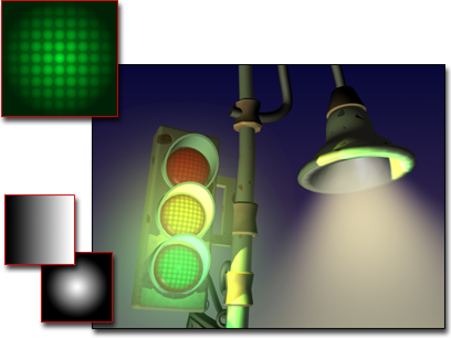
Gradient maps used for the stoplight lamps, and for the background of the scene
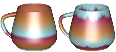
Gradient-mapped material tiled (left) and with noise (right)
Procedures
To change a gradient color:
- On the Gradient Parameters rollout, click a color swatch to display the Color Selector.
- Adjust the color.
- Click one of the other color swatches.
- Adjust the color.
To choose the kind of gradient:
- Choose either Linear or Radial.
A linear gradient shades from one color to another along a line. A radial gradient has one color on the inside and another on the outside, shading in a circular pattern.
To use a map for a color in the gradient:
- On the Gradient Parameters rollout, click a map button to assign a map to a color.
Alternatively, use the Slate Material Editor to wire a map to the Color 1, Color 2, or Color 3 component.
To adjust the position of the second color:
- Change the Color 2 Position value.
At the default value of 0.5, the second color is between the first and third colors. For a linear gradient, the second color's position ranges from the bottom at 0.0 to the top at 1.0. For a radial gradient, the second color's position ranges from the inside at 0.0 to the outside at 1.0.
Interface
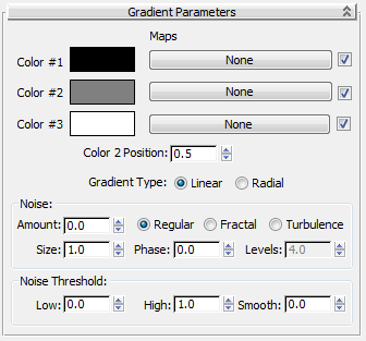
- Color #1–3
-
Sets the three colors that the gradient interpolates between. Displays the Color Selector. You can drag and drop the colors from one swatch to another.
- Maps
-
Displays a map instead of the color. Maps are blended into the gradient in the same way that the gradient colors are blended. You can add nested procedural gradients in each window to make 5-, 7-, 9-color gradients, or more.
The checkboxes enable or disable their associated maps.
- Color 2 Position
-
Controls the center point of the middle color. The position ranges from 0 to 1. When it is 0, color 2 replaces color 3. When it is 1, color 2 replaces color 1.
- Gradient Type
-
- Linear Interpolates the color based on the vertical position (V coordinate).
- Radial Interpolates based on the distance from the center of the map (center is: U=0.5,V=0.5).
With either option, you can rotate the gradient using the Angle parameters on the Coordinates rollout. UVW Angles are animatable.
Noise group
- Amount
- When nonzero (ranges from 0 to 1), applies a noise effect. This perturbs the color interpolation parameter using a 3D noise function based on U, V, and Phase. For example, a given pixel is halfway between the first and second color (the interpolation parameter is 0.5). If noise is added, the interpolation parameter would be perturbed by some amount so that it may become less or more than 0.5.
- Regular Generates plain noise. This is the same as Fractal noise with the Levels setting at 1. When the noise type is set to Regular, the Levels spinner becomes disabled (because Regular is not a fractal function).
- Fractal Generates noise using a fractal algorithm. The Levels option sets the number of iterations for the fractal noise.
- Turbulence Generates fractal noise with an absolute value function applied to it to make fault lines. The noise amount must be greater than 0 to see any effects of turbulence.
- Size
- Scales the noise function. Smaller values give smaller chunks of noise.
- Phase
- Controls the speed of the animation of the noise function. A 3D noise function is used for the noise. The first two parameters are U and V and the third is phase.
- Levels
- Sets the number of fractal iterations or turbulence (as a continuous function).
Noise Threshold group
When the noise value is above the Low threshold and below the High threshold, the dynamic range is stretched to fill 0–1. This produces a smaller discontinuity at the threshold transition and thus causes less potential aliasing.
- Low
- Sets the low threshold.
- High
- Sets the high threshold.
- Smooth
- Helps make a smoother transition from the threshold value to the noise value. When smooth is 0, no smoothing is applied. When it is 1, the maximum amount of smoothing is applied.