In this dialog box you can modify the grid and axis group properties as needed.
The Axes, parallel dialog box
| Option | Description | |
|---|---|---|
| The grid size | The top field defines the distance between the first and the last axis of the group. The number of axes changes accordingly. The field on the right defines the length of an axis. | |
| Balloon (Frame) | The labeling text can be displayed with or without frames. | |
|
None: 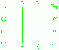 |
Edging: 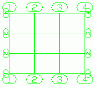 |
|
| Automatic label |
The axes can be labeled automatically or manually. If the automatic labeling box is not checked, the labeling for each single axis can be changed on the Single axis tab. For automatic labeling, the following parameters can be set:
|
|
| Option | Description |
|---|---|
| Group Index | Selects the group to modify. The selected group is highlighted in red. |
| Definition | Controls the number of axes in the selected group and the distance between them.
|
| Option | Description |
|---|---|
| Axis Index | Allows selecting an axis in the current group. The selected axis is highlighted in red. |
| Name | Displays the name of the selected axis. If the automatic labeling is turned off, the name can be changed. |
| Secondary Axis |
You can add a secondary axis to the right or to the left of a main axis and choose a label using the main axis name with a suffix and a prefix.
|
| Option | Description |
|---|---|
| Off | Completely hides the grid. |
| Standard |
Only the first and the last axis of the group have grips: end points and a center point. With the grip in the center, the group length can be modified, with the grips at the end the axis length (group width) can be modified. The last axis has an additional grip for moving the axis. 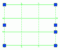 |
| Single axes |
Each axis has three grips: end points and a center point. The grip in the center allows moving the axis, the end grips allow modifying the axis length. 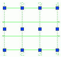 |
The Curved grid lines dialog box
In this dialog box, you can change the curved axis properties.
| Option | Description |
|---|---|
| The grid radius | The value field defines the curved axis radius. |
| Balloon (Frame) | The labeling text can be displayed with or without frames. |
| Label settings |
You can label the curved axis automatically, using numbers, small or capital letters. The following parameters can be set:
|
| Option | Description |
|---|---|
| Project grid vertically for model views and drawings |
Detailed Grids in All Limited View GA Drawings Grids that have this option checked can be detailed in limited view GA drawings, even when the grids are not actually included in the viewport. This applies to both plan and elevation details. When you create a new grid, this option is checked by default. For example, if the grids that are placed in the model on the bottom level of the structure have this option checked, they will be visible in a camera drawing that details the top level of the structure. Using this option, you can detail the same grids in GA drawings that show different levels of the structure, no matter if the position of the grids in the model is above or below the viewport of the detail.
 Note: The option is only available for horizontal grids, and it will be unavailable for grids created on planes that are not parallel to the world XoY plane. Non-horizontal grids cannot be detailed in GA drawings having viewports that do not include them. If you select several grids, including non-horizontal grids, you can check or uncheck the box for “Projected grid vertically for model view and drawings” for all the grids at the same time. In this case, a tooltip informs that only the horizontal grids in the selection will be affected by the change of the state of the option.
|
|
Projected Grids Model Views Grids that have this option checked are visible in activated model views which include the grids and in model views that do not include the respective grids but are positioned above or below the model grids. When you create a new grid, this option is checked by default. For example, if the grids that are placed in the model on the bottom level of the structure have this option checked, the respective grids will be visible in model views that do not include them but are positioned above them.
 If more than one model view is activated at the same time, the grids that have the option checked will be visible in all the activated model views.
 To prevent any unwanted modification done to the grids, you will not be able to modify the projected grids that are not actually enclosed in a model view. This includes modifying the grid properties, copying the grids, moving, or deleting the grids, even if the respective grids are visible and selectable in that activated model view. Note: The option is only available for horizontal grids, and it will be unavailable for grids created on planes that are not parallel to the world XoY plane. Non-horizontal grids will not be visible in model views that do not actually include them. If you select several grids, including non-horizontal grids, you can check or uncheck the box for “Projected grid vertically for model view and drawings” for all the grids at the same time. In this case, a tooltip informs that only the horizontal grids in the selection will be affected by the change of the state of the option.
|
Modify the grid properties
- Select the group of axes.
- Right click and select Advance Properties from the contextual menu.
- In the properties dialog box, select the Group tab.
- In the Group index field, enter the index of the group you want to modify.
- In the Number field, enter the desired number of axes.
- Select the group of axes.
- Right click and select Advance Properties from the contextual menu.
- In the properties dialog box, select the Total tab.
- Select Automatic label.
- Select the label type: numbers, small letters or capital letters.
- Additionally, you can define a label prefix and suffix.
- Select the group of axes.
- Right click and select Advance Properties from the contextual menu.
- In the properties dialog box, on the Display type tab, select Single axis. The axes of the group can be selected one by one.
- Select the grip in the middle of the grid axis you want to move.
- On the command line, define the moving value and press Enter.
- Select the group of axes.
- Right click and select Advance Properties from the contextual menu.
- In the properties dialog box, on the Total tab, disable the Automatic label option.
- On the Single axis tab, in the Axis index field, use the arrows to select the desired grid axis. The selected axis is displayed in red.
- In the Name field, enter the new label.