Level symbols are auxiliary objects used to identify the elevation of a point according to a reference level (height), often the sea level.
Use level symbols
Level symbols are placed in the model to identify level dimension points. The level symbols placed in the model can be taken into account at drawing creation using an adequate drawing style. When modifying the reference level, in the details, the level dimensions are automatically updated.
Example
Using level symbols you can define a global reference level that can be added to all measurements so that the model may be kept at the AutoCAD WCS.
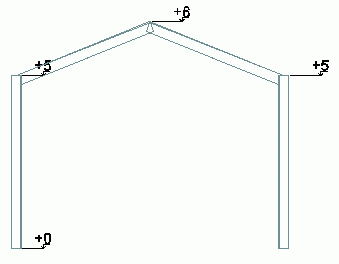
For a leveled structure, you can place a level symbol at each floor level.
Representation
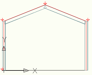
The level symbols are represented in the model as red arrows. You can modify their size in the level symbols properties dialog box.
Insert a level symbol
Inserts a small symbol into the model to identify the correct height at the selected reference point.
To access the command
In the Objects tab  Grid panel, click
 (Level Symbol).
Command line: _AstM4heightkote
- In the Objects tab Grid panel, click
(Level Symbol).
- Define the insertion point for the level symbol.
- The level symbol is created. The properties dialog box appears.
- Select the level symbols. You can use one of the selection methods.
- Right click and select Advance Properties from the context menu.
- On the Global tab, define the global reference level (the global height of the AutoCAD WCS origin).
- Select the level symbols to hide. You can use one of the selection methods.
- Right click and select Advance Properties from the context menu.
- On the Display type tab, select Off.
- The level symbols are hidden.
- Select the level symbols. You can use one of the selection methods.
- Right click and select Advance Properties from the context menu.
- On the Default tab, enter the desired size for the symbol.
- The size of the selected symbols changes. Newly created symbols will have the new size, by default.