In the Level Symbol dialog box you can define the properties of level symbols, such as size or representation type.
The Current tab
In this tab, the absolute and relative height are displayed. These values cannot be modified.
Absolute height
Displays the height value (z-coordinate) relative to a zero level.
Relative height
Displays the height value (z-coordinate) relative to the AutoCAD World Coordinate System.
Global tab
Datum level
Defines the zero level. A global height is assigned to the World Coordinate System origin.
Example:
If the site zero is at 1500 above sea level, enter 1500 for the Datum Level.
For all level symbols placed in the model, the Relative Level is measured from the site zero. For example, for a level symbol placed on a beam 4000 above the site zero, the Relative height will be 4000 and the Absolute height will be 5500.
Default tab
Symbol size
Defines the size of the selected level symbols, in model units. Newly created symbols will have the new size, by default.
Display type tab
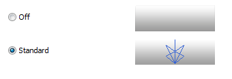
Off
Hides all selected level symbols.
Standard
Displays the level symbols in the Standard representation.