Learn how to automatically assign connections using a set of rules.
The first tab of the quick connection dialog, called Connection rule, handles the automatic assignation of connections that use a set of rules defined through the type/size of the beams and their relative position. The relative position for quick connections is defined by the node type, and the member characteristics.
Node Type
The type of beams that enter in the node. This is connected to both the relative position of the beams and their model role. The node type is presented as a predefined set of rules available in each quick connection profile.
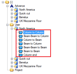
| Column to Column - Two columns (one along the other), vertical, with the column model role. | 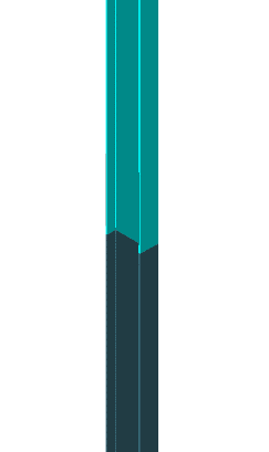 |
| Beam-Beam to Column - Two beams (one along the other), horizontal, with the beam model role, plus a column underneath them. | 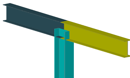 |
| Column to Beam - The column connects to the beam along the beam system axis (not in the start/end points). | 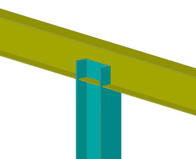 |
| Beam to Column - Typical column to beam connection. The horizontal beam needs to have the beam model role, while the column has the column model role. |  |
| Beam-Beam to Beam - Two beams (one along the other one), with a third beam connecting in the same node. All objects need to have the beam model role. | 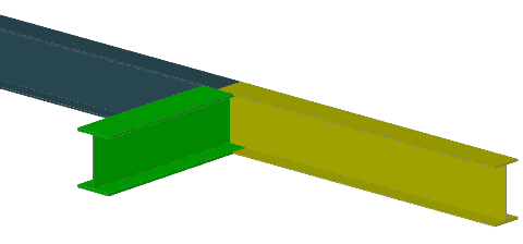 |
| Beam to Beam - A typical beam to beam connection where one of the beam ends along the other beam's system axis. | 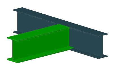 |
| Column end - A simple rule intended to work for base plate and end plate connections, creating connections on both ends of a standalone column. | |
Connection Members
Once you select a node type, a list is generated on the right side of the dialog, containing all the combinations of member types and their geometric condition.
The size of the list can be controlled through a set of buttons located on the top-right corner of the list. From here you can add or remove rules, and change their position in the list.
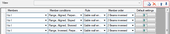
The order in the list is important - the lines are applied by going from top to bottom, so if the quick connection matches a combination set at line one for a set of beams, it will skip the following lines for the same rule.
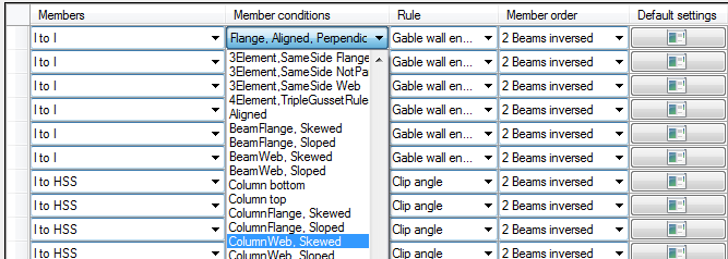
The member conditions set in those definition lines are the member type and the member condition.
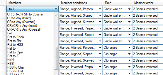
Member Type
In the member type combo-box, the quick connection configuration provides a wide set of definitions that combine the shape of beams that are part of the respective node. The beam shapes that can be set here are generic, like I-beams, angles, pipes, etc.
Member Condition
The second column offers the option to choose the member's geometric condition. This is intended to work for the second member only, and its geometric position in relation to the first one. For three-beam scenarios, like Beam-Beam to Column and Beam-Beam to Beam, the second member is actually the third one, the beam or the column, while the first member is represented by the two aligned beams.
|
The Column to Column most used one is Linear Aligned/Inversed |
Linear is the most common condition for this node type, as the two columns are aligned, together with… Aligned/Inversed - this attribute of the linear condition refers to the start/end points of the columns. Using both in succession in a definition ensures that the connection will be applied regardless of the modelling workflow used to create the two columns. |
|
The Column to Beam has a combination of Flanged, together with two sets of attributes Aligned/Inversed and Perpendicular/Sloped/Skewed. |
Flange - The column connects to the flange of the horizontal beam. Aligned/Inversed - Refers to the start/end point of the column. Depending on the direction used during modeling, this node between the beam and the column can occur on the column's start or end point. Defining rules with both those attributes ensures that regardless of the modelling, the connection will be made. Perpendicular/Sloped/Skewed - Relative orientation between the Column and the beam. |
|
The Beam to Column used a combination of Web/Flange with the relative position of the beam to the column. |
(Column)Flange/(Column)Web - refers to the relative position of the beam to the column, with both situations being accepted - Beam to Column web and Beam to Column flange. Perpendicular, Sloped, Skewed - relative orientation of the beam to the column. |
|
The Beam to Beam offers two different types of member conditions: a linear one, where the two beams are aligned, and a perpendicular/slope/skewed orientation of one beam against the second one. In addition to this, the conditions also offer the option to change between the web or flange and perpendicular/slope/skewed. |
|
|
Column End - Uses a special set of member conditions for the two positions of the base plate/end plate: Column Top and Column Bottom. |
|
Assign Automatic Rules
Once you set the geometrical constrains of the quick connection definition rule, an Advance Steel connection can be assigned to that rule.
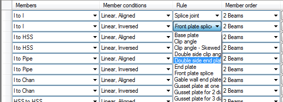
Set the connections using the Rule column and choose one of the options in the combo-box. The combo-box contains a set of available connections accepted by the quick connection.
Member Order
Together with the connection rule, the quick connection configuration also needs to set the selection order for the members that are part of the connection, based on the connection specifics.
You can make this setting using the Member order column:
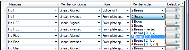
The two beam options are also available as an inversed setting. This is required to ensure that the connection will select the beams in the correct order.
Most of the configurations made for the two-beam nodes will be done using this option, because of how those options are named and because of their propose.
For example the Beam to Column node type is intended for the following beam scenario:
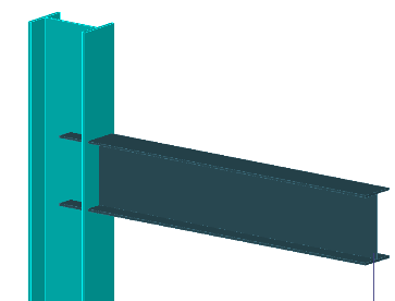
Here, one of the most used connections is the Clip Angle. When creating a clip angle connection in Advance Steel, the member selection required by the connection is: First the column and next the beam.
Because the node type is called Beam to Column, the column is the second member, and the beam is the first one. So for the Clip Angle to be created correctly, the member order needs to be reversed, the column is picked first, followed by the beam. The rule automatically chooses in this order, but the workflow should be followed in this case too.
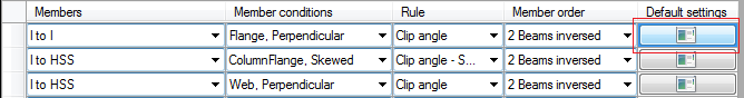
Default Settings
Another control over the created connection by each rule line can be done using the Default Settings option, available as a button on the definition line:
This will open a dialog that provides a set of override controls over the connection parameters. Not all the options in this dialog apply tp every connection, but all options are present, regardless of the connection set.
The checkbox next to each option turns the respective option on or off.
For bolts there is only one checkbox, which turns all the bolt fields on or off, so if they are turned on, then all the bolt parameters are controlled through the options found on this page.