Construction Plane
Creates a construction plane that specifies an alternative xyz origin and coordinate orientation.
A construction plane can be set as the active construction plane and used as an alternative to the world space coordinates for creating and transforming geometry. This is particularly useful when you are modeling at different angles.
Construction planes can also have images added to create Canvas planes and markups, and can be selected as input to tools that require a plane, for example Curve Planarize.

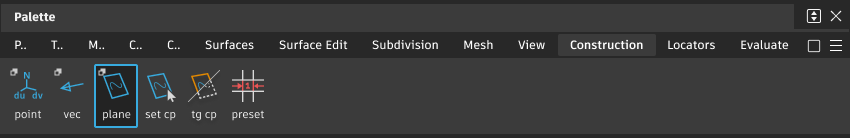
Access this tool from the Construction tool palette:
Related video
Construction Plane Options
Show Name
Show the name of the plane next to it in the viewport. This option is on by default.
Creation Type
The creation type can be set in the option window before hitting GO, or after using the action buttons in the bottom right corner of the viewport:
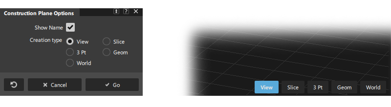
View - This is a 1-point construction plane where you specify the center point of the plane. The plane is oriented so that the Z-axis is parallel to the view vector. You can also snap the point to any geometry.
Slice - Specify 2 points. The third point is placed at the eye position so that you are looking at the plane from the edge. This type of plane is useful for defining cross sections.
3 Pt - This is the regular 3-point construction plane where you completely define the plane by inputting three points.
Geom - This is a 1-point construction plane where you specify the center point on geometry. The Z-axis is oriented along the surface normal or curve tangent.
World - This is a 1-point plane. You specify the center point and the three axes are oriented along the world axes. You can snap the point to any geometry.
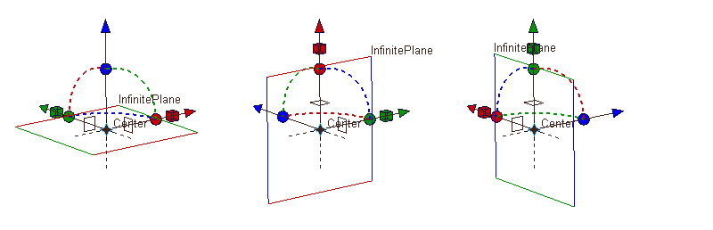
Viewport plane manipulator
View, Geom and World planes have a common manipulator that you can use to modify the position and orientation of the plane.
To re-display the manipulator at any time:
- Pick the construction plane (in the scene using Pick > Object or Pick > Component, or in the Construction Plane Editor)
- Select the Construction > Plane tool
 . The points and manipulator (if applicable to this type of plane) appear and can be modified.
To modify the manipulator, click a handle to select it (the handle becomes white), then either:
- Drag the handle to move/rotate/scale the plane.
- Type exact values on the keyboard.
- Click the geometry or the grid, while using a snap mode, to snap the axes of the manipulator to a specific position or orientation.
Manipulator Handles
 Drag an arrow handle to move the plane along an axis.
 Drag the circle icon or the dotted arc to rotate the plane around the axis with the same color.
 Drag a square handle to scale the plane along the x or y axis. The construction plane has no size in the z-direction and so cannot be scaled in z.
 Drag the center handle to move the plane freely.
 Click one of the square outline boxes to flip the plane to one of the two perpendicular orientations.
 Click a dotted axis line to reflect the plane across the X, Y, or Z axes.
Use Edit > Undo
 to undo changes to the manipulator.
Construction plane workflows
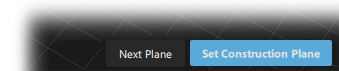
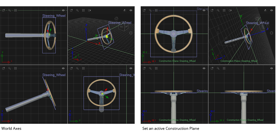
When creating a new plane, use the Set Construction Plane action button to set the new plane to being the active construction plane:
In the perspective view the grid will be redrawn to represent the construction plane coordinate system. The orthographic views will change to be in the coordinate directions of the construction plane.
After creating a construction plane, use the following tools to set and switch the active plane:
 Set Construction Plane. Pick the required construction plane before or after activating the Set Construction Plane tool.
 Toggle Construction Plane. Toggles between the world axes and the last set construction plane.
Tips for working with Construction Planes
If using many planes, use the Construction Plane Editor to name and manage the planes.
The construction plane can also be re-named using the Information Window.
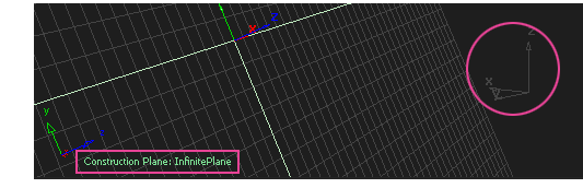
When working in a construction plane the active Construction Plane is displayed at the grid axis gnomon in each viewport. The world axes stay visible but are displayed in the grid color.
Use the Default View icon on the ViewCube to re-orient the view when switching between construction planes.
Use Plane View on the Navbar to match the viewing tools to the construction plane for easier view manipulation. See NavBar tools.
Use the View > Look-At tool or the ViewCube Look At tool to re-orient the perspective view to look down the z-axis of the construction plane.
To hide or show construction planes use Display > Toggles > Construction Objects.
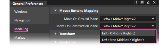
Mouse behaviour when using transform when using a construction plane is specified in the General Preferences:
Snap to the intersection of a curve/edge and a plane
If True Intersections is checked in Curve Snap Options, and you drag the snap point close to the construction plane, a yellow cross appears on the plane indicating that the snap point is precisely at the intersection point.