All door/window assembly grids, including the primary grid, can have mullion definitions. The mullions of a door/window assembly are the edges between the grid cells. You can define the mullions by specifying a width and depth or by selecting a profile from which the mullion is extruded.
Because door/window assemblies can contain multiple nested grids with different mullions, it is helpful to use a naming convention for grid mullions that indicates the grid location or purpose within the door/window assembly. For example, L3-FL1- Window Mullion identifies a mullion for a window in a third-level grid on Floor 1.
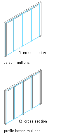
Specifying default and profile-based Door/Window Assembly mullions
You create mullion definitions for a specific door/window assembly style and those definitions can be assigned only to mullions in door/window assemblies of that style. You can create as many mullion definitions as you want and then assign the definitions to mullions as needed. If you have nested grids, each grid has its own mullions. A default mullion definition, which you can modify and assign as needed, is used for any unassigned mullions.
Materials and Display Properties for Mullions
If you do not use materials to control the display properties of mullions, you can specify their display properties in the door/window assembly style. The layer, color, linetype, and other display properties of the default mullion are applied to all mullions unless you create a custom display component for each definition. You can then control the display of each mullion definition independently.