- Double-click the door you want to change.
- In the Properties palette, click the Display tab.
- Change the display properties as needed:
Display Property Description How to Set Display component Lets you select individual object components for editing. If no component is selected, the change applies to the whole door. Select *NONE* from the drop-down list. This allows you to make a change to the entire door. Display controlled by Displays the currently selected display source. Options
- This object: Display properties are used for this object only.
- Door Style: Display properties come from the door style
- Drawing default settings: display properties come bfrom the global drawing settings.
Display representation Shows you which display representations are active in the current drawing view. Multiple display representations can be turned on. For example in Plan view, both plan and threshold symbol plan display representations are visible. Select the display representation in which you want to change a display property from the drop-down menu. If the list is greyed out, the view only has one associated display representation. Use cut plane of containing object when anchored (Plan views only) Specifies whether a selected door will use the cut plane of the wall or door/window assembly it is anchored to Select Yes or No from the drop-down menu. Straight Swing (Plan Views only) Specifies whether to display the swing of a selected door as a straight line in the current display representation. Illustration
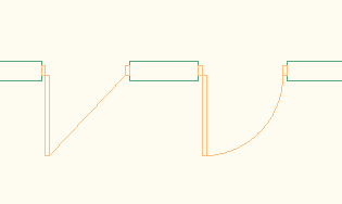
Straight swing (left) and curved (right)
Select Yes or No from the drop-down menu. Override Swing Angle/Swing Angle (Plan and Elevation views only) Lets you define an override to the swing angle that was defined in the Door Properties. For Override Swing angle, select Yes. Then, enter a door angle under Swing Angle. Custom Block Display Custom blocks are AutoCAD blocks that you can add to a specific display representation of a door, like a door knob, or a custom panel. In this worksheet, you can add, edit, disable, or remove custom blocks from the door. Click the Custom Block Display worksheet (  ), and add blocks to the door in the selected display representation.
 Threshold Dimensions (Threshold Plan only) Lets you specify the depth and extension of the threshold display. Click the Threshold Dimensions worksheet ( ), and add values for the depth and extension. Threshold Symbol (Threshold Symbol Plan Only) Lets you define a Threshold symbol. Click the Symbol worksheet ( ), and select one of the available symbols - Heel, Passthrough, Threshold, or no - in the list. Muntins (Elevation and Model view) Door muntins are secondary framing members that hold multiple lights in door glass. AutoCAD Architecture 2024 toolset provides an easy way to create muntins with different layout patterns.This worksheet lets you add, edit, disable, or remove muntins from a door. Click the Muntins worksheet ( ), and add or remove muntins. Reverse Handing (Elevation views only) Click the drop-down list and select Yes or No. Single Line Panel (Plan High Detail view only) Lets you display the door panel as a single line Illustration
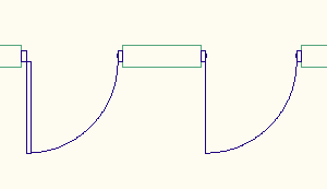
Single line door panel (right)
Click the drop-down list and select Yes or No. Frame Display (Plan High Detail Only) Lets you display the door frame with different representations in Plan High Detail Illustration
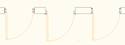
Click the Frame Display worksheet, and select the desired Frame representation there.