Use this procedure to change the patterns for the Plan, Hatch, and Section Hatch components of a material definition.
- Click
 .
. 
The Style Manager is displayed with the current drawing expanded in the tree view.
- Click Multi-Purpose Objects Material Definitions.
- Select the material definition you want to change.
- Click the Display Properties tab.
- Select the display representation where you want the changes to appear, and verify that Style Override is checked.
The display representation in bold is the current display representation.
- If necessary, click
 .
. - Click the Hatching tab.
- Select Plan Hatch or Section Hatch, and click the setting for Pattern.
- Select the hatching for the component:
If you want to… Then… select a hatching pattern that is available in the software select Predefined for Type, and then select a pattern. select a custom pattern select Custom for Type, and then enter the name of the custom pattern. If necessary, click Browse, and navigate to the location where the custom pattern file is located. select single hatching select User-defined for Type, and clear Double Hatch. select double hatching select User-defined for Type, and select Double Hatch. select solid fill select Solid Fill for Type. - Click OK.
- Click Scale/Spacing, and enter a value that determines how the selected pattern is repeated.
- Click Angle, and enter the angle for the selected pattern.
- Click Orientation, and specify how the hatching is oriented:
If you want to… Then… orient the hatching to the object, regardless of the object rotation select Object. orient the hatching to the World Coordinate System select Global. 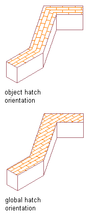
Specifying surface hatching orientation
- Click OK.