When a profile is used to extrude objects or components, you need to set the following parameters:
- the position of each edge in a profile (left, right, back, discard, none)
- the axis along which the object is extruded from the shape of the profile
These settings determine how surface hatching is applied to objects created from the profile and how the objects are extruded from the two-dimensional (2D) profile.

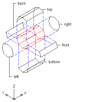
Face assignments from edges extruded in the X direction

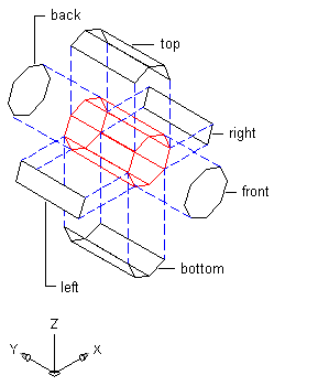
Face assignments from edges extruded in the Y direction

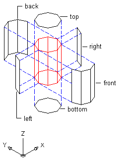
Face assignments from edges extruded in the Z direction
Note: Objects already created from the profile change when you change profile edges or the axis of extrusion.
- Click


 .
. 
- Select the profile you want to change.
- Click the Profile Edges tab.
- Select an edge, and specify its position:
If you want to… Then… let the software determine the position of edges click Calculate Default Edge Positions. You can then override the position of individual edges, if necessary. select a position for an edge select the setting for Edge, and select a new position. exclude an edge from surface hatching select the setting for Edge, and select None. discard an edge select the setting for Edge, and select Discard. - Specify the axis of extrusion based on the type of object created from the profile:
If you want to… Then… create a profile for roof slab or slab fascia, wall sweeps, or railings select X for Extrusion Direction. create a profile for a slab soffit, or opening frame select Y for Extrusion Direction. create a profile for an extruded mass element select Z for Extrusion Direction. - Click OK.