Sometimes we might work harder than necessary, leaning on the techniques we know and overlooking tools that might simplify workflows. Take the simple task of changing the length of a line or arc. Does this process sound familiar? You draw a temporary line, extend (or trim) to it, and then erase the temporary line. Let me introduce you to two AutoCAD commands designed to eliminate those extra steps: STRETCH and LENGTHEN.
Stretching Multiple Objects
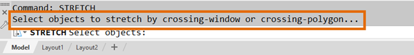
The STRETCH command has the distinction of being the only modify command that requires objects to be selected in a specific way. Let's explore why it has these selection requirements.
When stretching an object, the concept is that one end is going to remain fixed (or pinned) while the other is repositioned. To accomplish this, STRETCH interacts with an object’s points (endpoints, vertices, center points, intersections, insertion points, and so on), so simply selecting the object isn’t enough; STRETCH needs to know which points to modify.
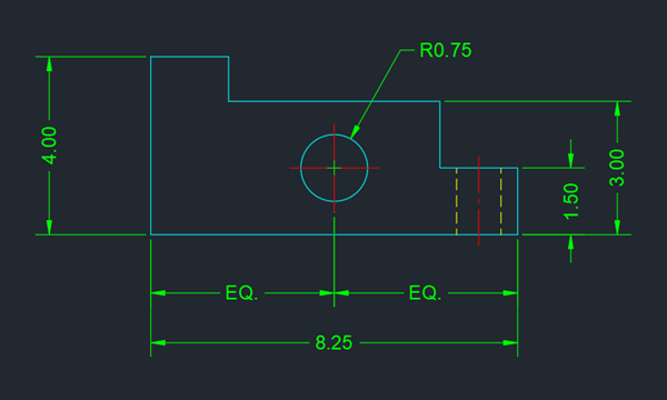
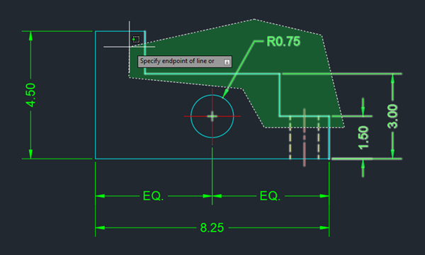
For our exercise, let's make a few changes to a simple machined part.
- Create a drawing similar to what is shown below.
- Click
. Find
You can also enter STRETCH at the Command prompt.
- Create a crossing selection window by specifying two points going from right to left to select the geometry to stretch.
Note: See Have Your Tried: Window, Fence, Lasso, and More for tips on selecting objects.
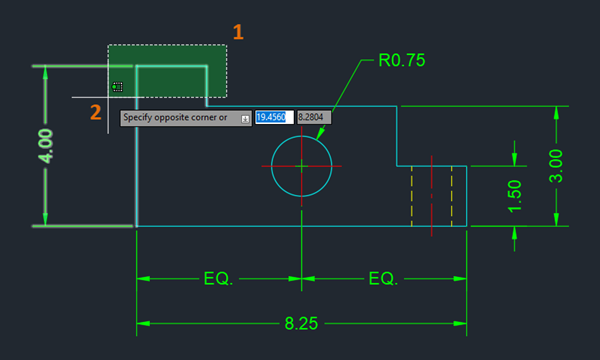
Using a crossing selection method not only selects one or more objects to be stretched but more importantly encloses all points that are to be repositioned.
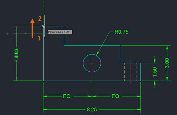
- At the
Specify base point prompt, choose a reference point (1) and drag the objects to the desired location (2).
 Note: If you want to constrain the direction while stretching, you can hold down the Shift key to temporarily toggle ortho mode on, or try combining object snaps (if applicable) with Ortho (F8) or Polar tracking (F10) and Object Snap tracking (F11). To learn more about these topics, see the links provided at the end of this article.
Precision Selections
Stretching Various Objects
As explained earlier, crossing selection methods help to select the objects to modify and the points to be stretched. When working with lines, polylines, or arcs, these points are easy to see and select. But what happens when the STRETCH command encounters a circle?
When interacting with blocks or xrefs, the STRETCH command only modifies the placement of a block or xref if the crossing selection includes its insertion point.
Let’s do a quick exercise.
- Click . Find
- On the Tool Palettes window, click Architectural tab.
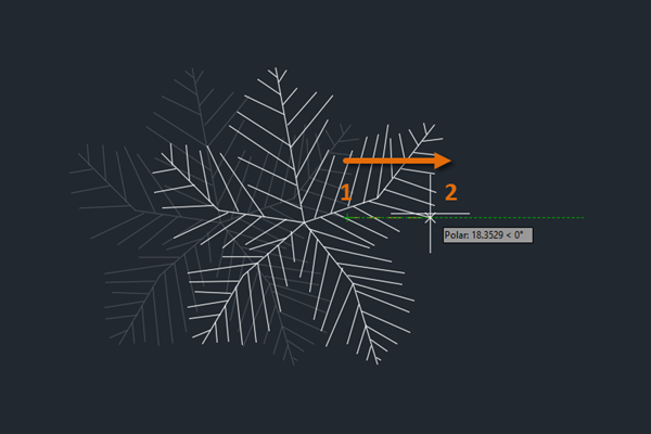
- Select the Trees - Imperial block from the palette and click anywhere in the drawing area to place the block.
The default view is a plan view of a palm tree.

- Select the block.
The insertion point grip (the square grip at the center of the tree) displays. This is important to know when using the STRETCH command.
 Note: If you don't see the insertion point grip after selecting the block, set the GRIPBLOCK system variable to 0.
 - Press Esc to deselect the block.
- Click . Find
- Select the block using a crossing window. Make sure to include its insertion point in the selection.
The entire block geometry doesn't have to be enclosed in the crossing selection.

- Specify a base point (1) and then specify a second point (2).
The block is moved rather than its geometry stretched.
 Note: Other objects with insertion points (multiline text, xrefs, arrays, images, PDF attachments, and so on) behave in a similar fashion. The objects are affected by a STRETCH only if the insertion point is enclosed by the crossing selection method.
The LENGTHEN Alternative
The word stretch is commonly defined as a process of making something longer, which the STRETCH command can certainly do. There is also a more specialized command, LENGTHEN, that you can explore. The primary advantage LENGTHEN offers is the ability to change the length of an object while retaining its angle (for lines and polylines) or its radius (for arcs and ellipses). Let's try this simple exercise.
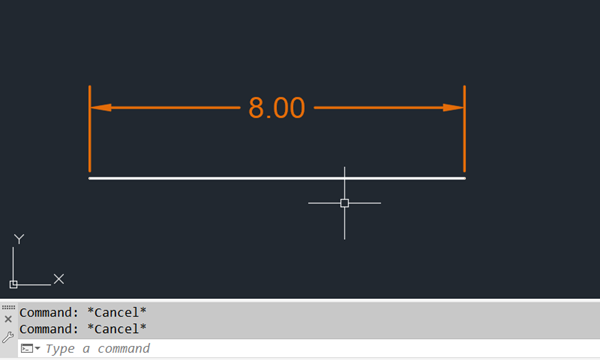
- Draw a line or polyline that's eight units long.
An associative dimension was added to show the length as the line changes.
- Click
.
Find
Alternatively, at the Command prompt, enter LENGTHEN.
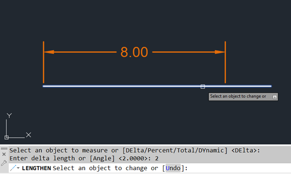
At the Command prompt, you can optionally select an object to find its current length.
- At the Command prompt, enter
DE or choose the Delta option.
When using the Delta method, you specify how much the current length should change.
- Enter a delta of 2.
- Select near the end of the line to define the direction in which it should be lengthened.
 Note: If your COMMANDPREVIEW system variable is set to 1, you will see a preview of the final result before selecting the line. For more information see Have You Tried: Command Preview.
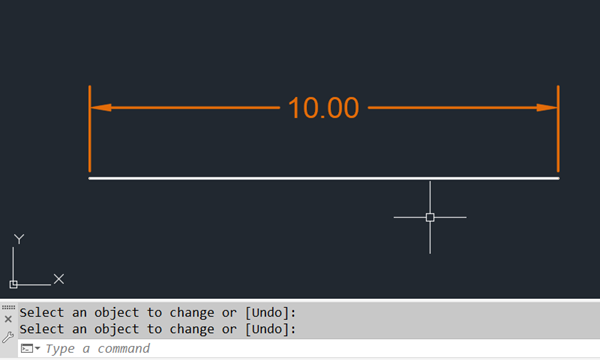
- (Optional) Continue selecting lines that you want changed by two units.
- Press Enter to end the command.
- Percentage. Specifies the amount of change as a percentage of the object’s current length.
- Total. Specifies the new length by providing the desired final length.
- Dynamic. Specifies the amount of change by dragging your cursor.
Stretch and Lengthen Objects with Grips
Summary
With a little practice, STRETCH and LENGTHEN will soon become staples in your AutoCAD toolbox. Forming a new habit takes time and intention. Investing a little time with STRETCH and LENGTHEN just might stretch your abilities and lengthen your skill set. Sorry, couldn’t resist.
Stretch and Lengthen Related Commands and System Variables
| Command | Description |
|---|---|
| LENGTHEN | Changes the length of objects and the included angle of arcs. |
| STRETCH | Stretches objects crossed by a selection window or polygon. |
| System Variable | Description | Default Value | Saved In |
|---|---|---|---|
| COMMANDPREVIEW | Controls whether a preview of the possible outcome of certain commands is displayed. | 1 | Registry |
| GRIPBLOCK | Controls the display of grips in blocks. | 0 | Registry |
| GRIPS | Controls the display of grips on selected objects. | 2 | Registry |