Oftentimes, we make mistakes or overlook some things when working with objects in a drawing. For example, you may have assigned an incorrect value to an object or created an object on the wrong layer. Or maybe you need to update a drawing that someone else created. Although you can erase and redraw an object, in most cases it's easier to just modify the properties of the existing object.
- Use the Properties palette
- Use the Quick Properties palette
- Use the Properties panel on the ribbon
- Change the object's layer
- Copy and paste properties from one object to other objects (MATCHPROP command)
Note: For more information about matching object properties, see Have You Tried: Matching Properties.
In this Have You Tried article, we are only going to explore how we can obtain drawing information and edit object properties using the Properties palette.
The Properties Palette
Every AutoCAD object has its own set of properties. General properties such as color, layer, linetype, linetype scale, lineweight, and some others are common to most objects. Some objects have specific properties for themselves.
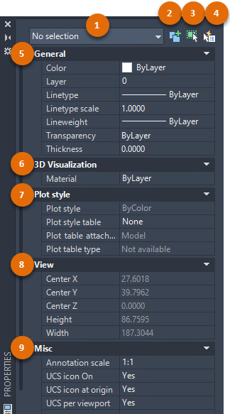
| Number | Name | Description |
|---|---|---|
| 1 | Object Type Filter | Displays the type of objects that are selected. Use the object type filter drop-down list when you select multiple types of objects, and want to modify the properties of a single object type at a time. |
| 2 | Toggle Value of PICKADD System Variable | Turns the PICKADD system variable on (1) and off (0). When PICKADD is on ( ), each object selected, either individually or by windowing, is added to the current selection set. When PICKADD is off ( ), each object selected, either individually or by windowing, is added to the current selection set. When PICKADD is off ( ), selected objects replace the current selection set. ), selected objects replace the current selection set.
Note: When PICKADD is set to 0, you can hold the Shift key to add objects to the current selection set.
|
| 3 | Select Objects | Selects desired objects using any selection method. The properties common to the selected objects are displayed in the Properties palette. You can then modify the properties of the selected objects in the Properties palette, or you can make other changes to the selected objects by entering an editing command. |
| 4 | Quick Select | Displays the Quick Select dialog box. Use Quick Select to create selection sets based on filtering criteria. |
| 5 | General | Displays the general properties of the selected object or the settings of the current drawing (when nothing is selected). This section also includes a set of Layer tools. |
| 6 | 3D Visualization | Displays the 3D visualization properties for the current drawing or selection. |
| 7 | Plot Style | Displays the plot style settings including the plot style table options that can be assigned to the current drawing or to a selected object. |
| 8 | View | When no object is selected, displays the current view settings. |
| 9 | Misc | Displays other drawing settings and viewport properties such as the current annotation scale, UCS icon display settings, and the visual style. |
Display the Properties Palette
- View and modify the current properties to be used for all new objects.
- View and modify the properties for a selected object.
- Access the common properties that apply to all selected objects.
- View the drawing or viewport properties when no object is selected.
- Click
 Find
Find
- At the Command prompt, enter PR (PROPERTIES command).
- Right-click a selected object and select Properties.
- Press Ctrl+1.
The Properties palette can be resized, docked to either side of the drawing window, moved to another location, or placed onto a secondary monitor.
Edit the Properties of an Object
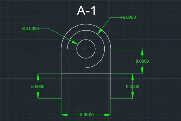
In addition to displaying the current settings of the drawing, the Properties palette is a powerful tool for editing object properties. In this exercise, we make some property changes to a simple mechanical part.
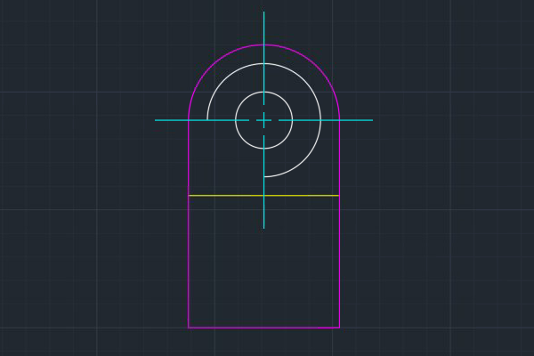
- Draw something similar to what’s shown below.
You may also open a drawing of your own.
- If the Properties palette is not already open, click
Find
Tip: Press Ctrl+1 to easily show or hide the Properties palette.
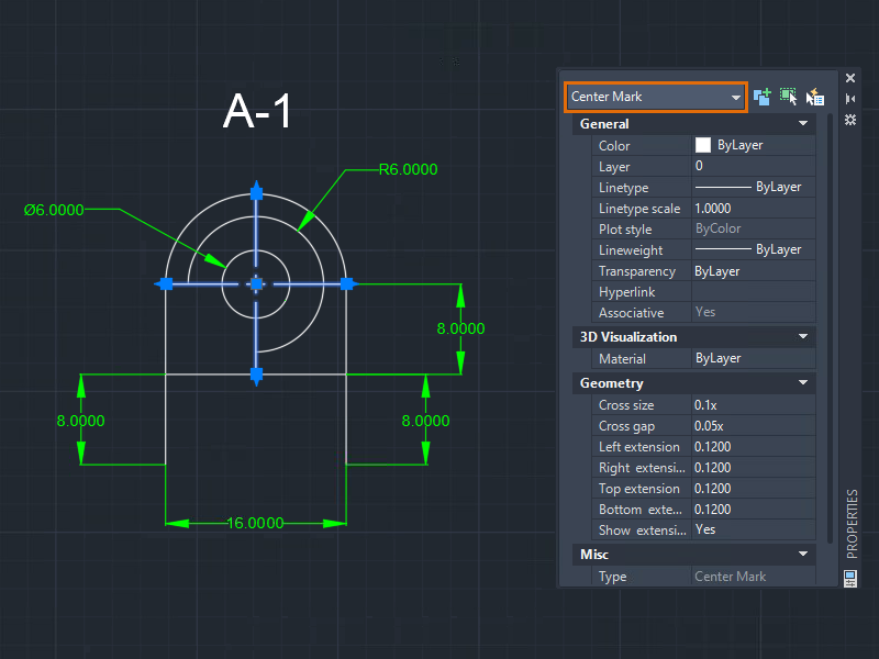
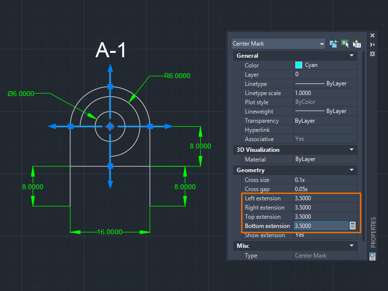
- Select the center mark.
The properties of the selected center mark display in the Properties palette.
For more information about selecting objects, see Have You Tried: Window, Fence, Lasso, and More.
- In the Properties palette, under General, select a color, for example, Cyan.
- To extend individual centerline extensions, under Geometry, change the Left, Right, Top, and Bottom Extension values. For this example, I changed all extensions to
3.5000.
 Tip: You can also uniformly change the length of all four centerline extensions using the multi-functional center grip of the center mark. To learn more techniques about grip-editing, see Have You Tried: Just Grip It!.
 - Press Esc to clear the selection.
- Let's try a different object. Select the polyline.
Notice that the properties available for the polyline are different from those of the center mark.
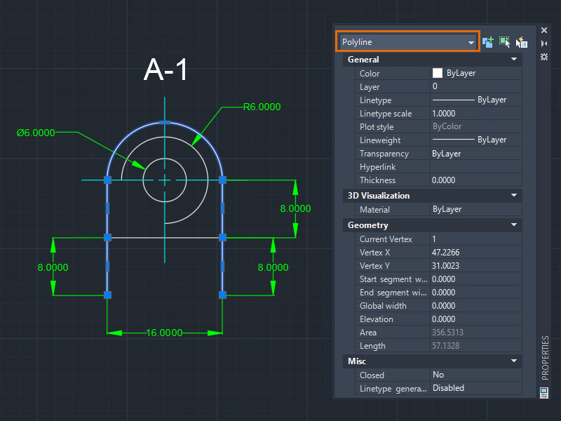
- To adjust the first vertex, in the Properties palette, under Geometry, click the Current Vertex box.
An X marker indicates the vertex of the polyline that you're editing. You can only edit one vertex at a time.
- From the Current Vertex property, select 1.
- Change the Vertex X/Y values and see what happens. In this example, I changed the Vertex Y value (from 31.0023 to
25.0023) to move the first vertex vertically downward.
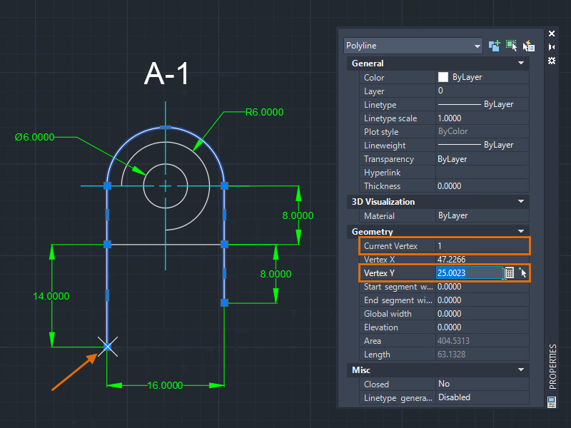 Note: The dimension automatically updates when the vertex is changed.
 - Select another vertex by clicking the arrows of the spinner next to the Current Vertex value. In this example, I chose the last vertex and specified the same Vertex Y value as the first vertex.
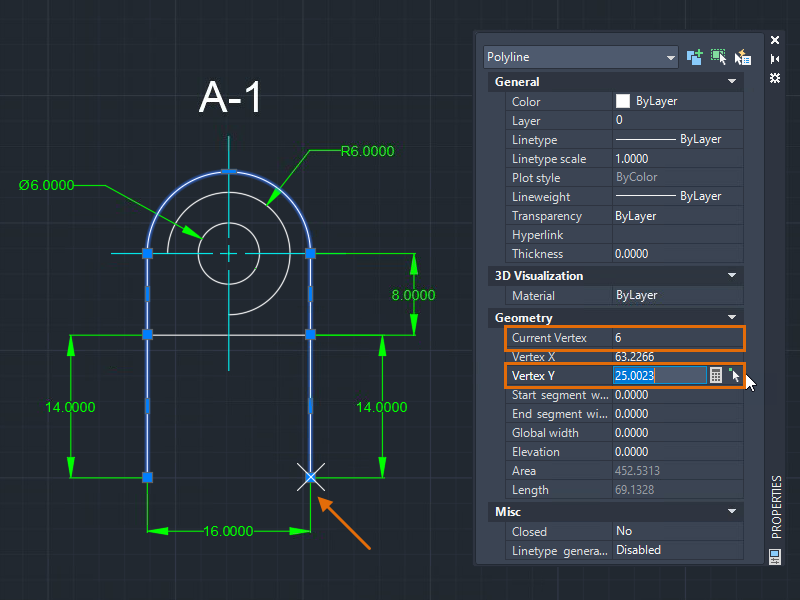
Now, the first and last vertices of the polyline are aligned. This method of editing the vertices is useful when you know the absolute coordinates you want.
Polylines consist of one or more line or arc segments. A vertex defines the start and endpoint of a segment. The order of the vertices follows how the polyline was created.
Let's say you want to stretch the individual segments of the polyline.
Edit the Properties of Multiple Objects
When you select multiple objects, only the common properties are displayed in the Properties palette. Some of these properties can be modified, and any change to a property is applied to all objects in the selection set. Use the Properties palette to set a property on multiple objects to the same value.
If all selected objects share the same value for a property, then that value is shown in the Properties palette. Otherwise, if the selected objects have different values for a property, *VARIES* is shown in the Properties palette.
- Select objects of different types, for example, a line and a polyline.
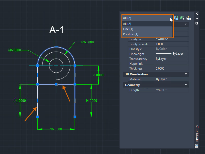
The Object Type Filter drop-down displays the number and types of selected objects. The Properties palette displays both editable and read-only properties. A property can be read-only (grayed out) because its value is automatically calculated or assigned, or it depends on the value of another property.
- Create a set of layers in the Layer Properties Manager first so that they're available for assignment in the Properties palette. To learn more about layers, see Layers in the Hitchhiker's Guide.
- Assign the selected objects to a layer, for example,
LINES.
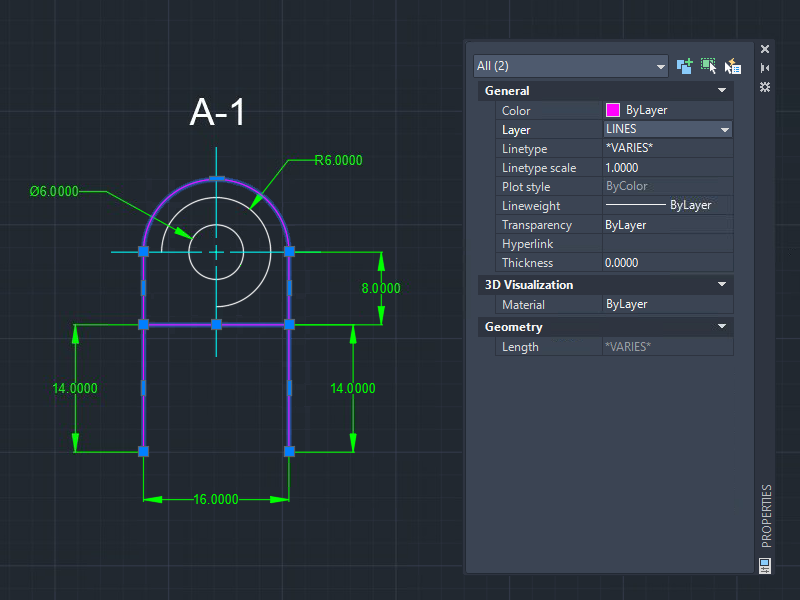
Changing a property of selected objects to ByLayer inherits the property values of the current layer. Because the Color property of the selected objects is set to ByLayer, the objects now display the color defined for the LINES layer.
- You can override any property assigned to a layer. Let's say you want to change the color of an object but keep it on the same LINES layer. Do the following:
- Press Esc to clear the selection.
- Select the desired object, for example, a line.
- In the Properties palette, click Color and select a different color (for example, Yellow) from the drop-down list.
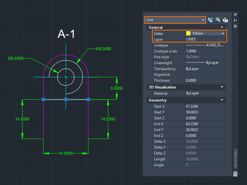
The object is displayed with the new color, regardless of the color assigned to the layer.
- Try changing other properties available for your selection set such as linetype, lineweight, and so on.
Note: Linetypes must be loaded first in the drawing with the Linetype Manager. Otherwise, they won’t be available in the Properties palette. For more information about linetypes, see Linetype Manager.
Filter Objects by Type
Sometimes, we need a quick and simple way to filter objects. The Properties palette allows you to filter objects and apply changes to the selected objects by type.
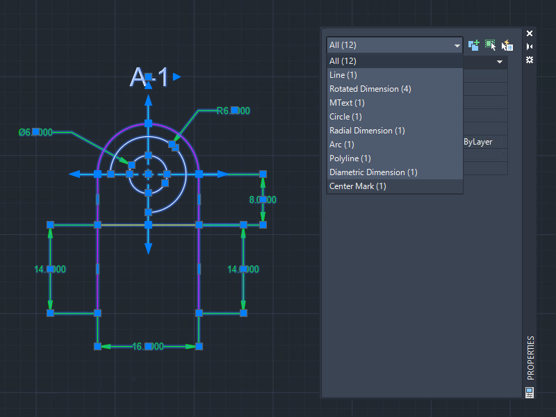
- With the Properties palette open, select all objects in the drawing.
I continue working with the drawing created earlier. If you like, you can open a more complex drawing for this exercise.
- Click the Object Type Filter drop-down to view the object types and the number for each type in the selection set.
- Select an object type from the drop-down, for example, Rotated Dimension, specify the following:
- Layer: DIM
- Text height: 1.0000
Note: The selection set does not change even after selecting an object type. However, any information displayed in the Properties palette and any changes made only apply to the selected object type in the filter. - You can't select multiple object types using the object type filter on the Properties palette. To filter your selection results even further, click Quick Select to quickly create a selection set of objects based on specified criteria.
Find Geometric Information
Obtaining geometric information can be done in many ways, for example, using dimensioning tools. But depending on the situation or complexity of the geometry, you might find it easier to view the properties of an object and then change the values in the Properties palette.
Let’s assume that you received a drawing with geometry that needs to be updated or converted to your company’s standard.
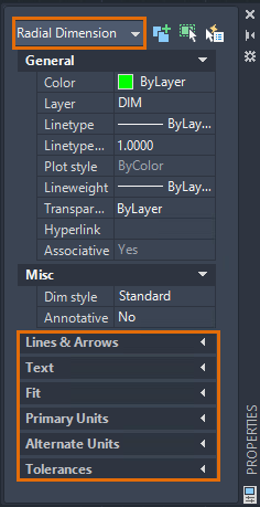
- Select all dimensions.
Although the dimensions are displayed with the same color, you can see that the layer and linetype assigned to the dimensions vary.
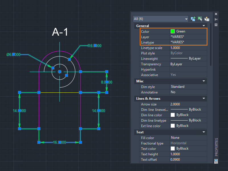
- To ensure proper layer standards, for example, DIM layer, are used for the dimensions, specify the following:
- Color: ByLayer
- Layer: DIM
- Linetype: ByLayer
You can change other properties to ByLayer, as required by your company.
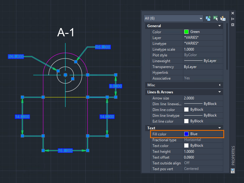
- (Optional) Apply a background mask color to the dimension text. Under Text, Fill Color, select Background from the drop-down or select a color.
- Select an object, for example, an arc.
- Review its properties. You can easily find the calculated area and the length of the arc without using any command.
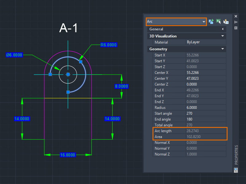
- Change the radius, angles, or other related properties, as desired.
Create a Closed Object
One key consideration to successfully apply a hatch to an object is that its boundary should be closed. Although, you can specify settings such as the gap tolerance to allow hatching inside an open object, it is recommended to ensure that hatch areas are closed.
Sometimes it's hard to find and fix small boundary gaps specially when working in large or complex drawings. These unwanted gaps may prevent you from creating the desired hatch. With the Properties palette, you can easily close (or open) objects like polylines or splines.
- With the Properties palette open, select the polyline.
I continue working with the drawing created earlier. If you like, you can open a more complex drawing for this exercise.
- In the Properties palette, under Misc, click Closed and select Yes.
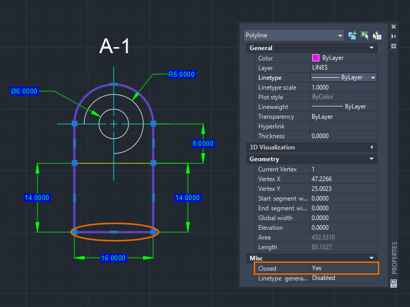
When you close the polyline, a line segment is created from the last vertex of the polyline to the first vertex. Closing the polyline using this method does not add a vertex to the object.
Check for Non-Coplanar Objects (AutoCAD Only)
In AutoCAD, all 2D geometric objects are created on the XY plane. But sometimes, objects get moved along the Z-axis either by design or by mistake. When objects are not on the same plane, object snaps might not work as expected or you might encounter an error when performing tasks such as creating fillets.
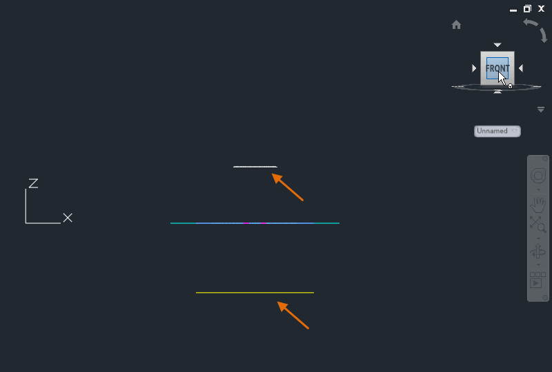
For this exercise, let’s move some objects along the Z-axis. To do this, you can orbit around or rotate the user coordinate system (UCS), and then move some objects along the Z-axis. For more information about the user coordinate system (UCS), see Have You Tried: Using the UCS for 2D Drafting.
- With the Properties palette open, click
 and select all the objects in the drawing. Press Enter.
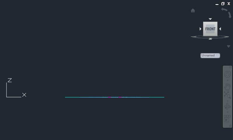
- On the ViewCube, click Front.
- Click the Object Type Filter drop-down and go through each object type. Check the Z-axis coordinate values.
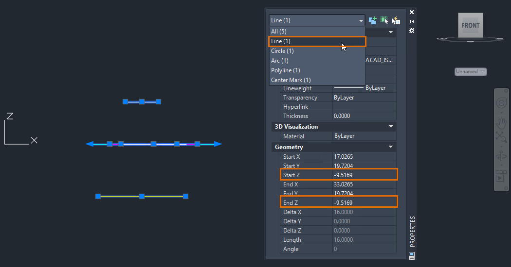
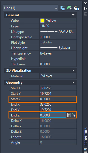
- In this example of the line object, change the Start Z and End Z values to
0 (zero).
- Select another object type and review its Z-axis coordinate values.
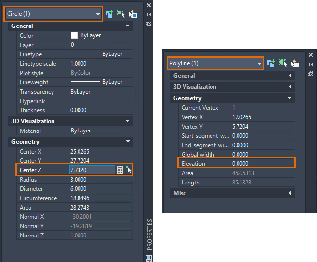
Different objects will have different Z-axis property names. An object may have one or a combination of the following properties: Start Z, End Z, Position Z (mtext), Center Z (circles), or Elevation (polylines).
- Change any non-zero Z-axis coordinate value to
0.
All your objects are now on the same XY plane.
If the Z-axis coordinate has values other than zero or *VARIES* as a value, it means that one or more of the selected objects are non-coplanar.
Undo Properties Palette Changes
To undo the changes in the Properties palette one at a time, right-click anywhere on the palette and select Undo. You might not see the Undo option if you right-click on a text box in the palette.
Pressing Ctrl+Z while actively editing on the Properties palette does not undo the recent change.
Summary
The Properties palette is an essential tool for editing and obtaining geometric information. Simply select one or more objects and view object property changes in real-time with the palette. You might be surprised to find something in the Properties palette that you were not aware of before.
Related Commands and System Variables
Here are some frequently used commands and system variables related to Properties palette.
| Command | Description |
|---|---|
| PROPERTIES | Controls properties of existing objects. |
| PROPERTIESCLOSE | Closes the Properties palette. |
| QSELECT | Creates a selection set based on filtering criteria. |
| System Variable | Description | Default Value | Saved in |
|---|---|---|---|
| PICKADD | Controls whether subsequent selections replace the current selection set or add to it. | 2 | User-settings |
| PROPERTYPREVIEW | Controls whether you can preview the changes to currently selected objects when you roll over drop-down lists and galleries that control properties. | 1 | Registry |
| PROPOBJLIMIT | Limits the number of objects that can be changed at one time with the Properties and Quick Properties palettes. | 25000 | User-settings |
| PROPPREVTIMEOUT | Sets the maximum amount of time available for generating a property preview. | 1 | Registry |