Displays the devices in the project, organized by Installation and Location. Devices include standard components, terminals, PLC modules, and cable markers.
Find Command entry:
AEPROJECT
 Select the Location View tab.
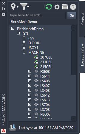
List of Options
The following options are displayed.
Buttons
-
Filters the tree view by Installation and Location.

-
Refreshes the component tree and the Details and Connections pane based on the AutoCAD Electrical toolset data.

-
Opens the Details and Connections pane. The Details tab shows the component values such as Installation, Location, and catalog. The Connections tab shows wiring information for the components. Right-click to change the fields to display on each tab.

Electromechanical Buttons
If the project is part of an electromechanical association, extra buttons are available.
-
Filters the tree view by component link status.

-
Opens the Sync Settings dialog box, which allows you to create your synchronization task. You can create synchronization schedule tasks to run at regular intervals.

-
Syncs the drawing tree with the Inventor data. The date and time of the last refresh displays next to the icon.
 Note: The button is at the bottom of the palette.
Search
Searches the component tree and displays only those devices that match the search text.
Component Tree
Displays a list of standard components, terminals, PLC modules, connectors, and cable markers. The top node in the tree represents the entire project. Each node under the project represents an Installation value. The nodes under each Installation represent the Location values within that Installation.
The various device types are represented differently in the component tree. When inserting electrical components, it is recommended that you should have unique names (installation code, location code, and component tag), pins, and terminals numbers. For example, if you have cable markers in your drawing, which has duplicate values for cable tag, then you may experience unexpected behaviour of the component in the component tree view and in the connections tab. This is more commonly observed for terminals and cable markers in Location View.
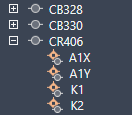
- Standard Component
 Tag value. Expand to view assigned pins.
- Terminal
-
 Tagstrip value: terminal number. A multi-level terminal lists each terminal number separated by a comma. Expand to view the level descriptions.
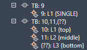 Note: Terminals that take on the wire number show the wire number in place of a terminal number.
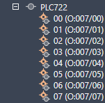
 - PLC
 Tag value. Expand to view each pin and address value.
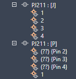
- Connector
 Tag value separated into two rows, one for the plug side and one for the jack side. Expand to view the pins.
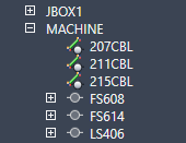
- Cable
 Tag value.
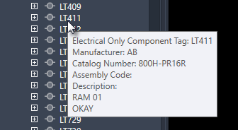
- Child
- A child component is excluded from the tree until the parent is inserted.
Electromechanical Status Icons
If the project is part of an electromechanical association, the icon in front of each device indicates both the device type and its link status.
-
Indicates an AutoCAD Electrical toolset component not linked to an Inventor component.

-
Indicates an Inventor component not linked to an AutoCAD Electrical toolset component.

-
Indicates linked AutoCAD Electrical toolset and Inventor components, with no mismatches in data.

-
Indicates linked AutoCAD Electrical toolset and Inventor components, but there is some mismatch between the data.

-
Indicates an AutoCAD Electrical toolset cable not linked to an Inventor cable.

-
Indicates an Inventor cable not linked to an AutoCAD Electrical toolset cable.

-
Indicates linked AutoCAD Electrical toolset and Inventor cables, with no mismatches in data.

-
Indicates linked AutoCAD Electrical toolset and Inventor cables, but there is some mismatch between the data.

Shortcut Menu Options
Right-click an installation, location, or device node to display a shortcut menu with relevant options.
- Expand All
- Expands all nodes including device nodes.
- Collapse All
- Collapses all nodes including device nodes.
- Surf
- Opens the surf dialog box for the device tag.
Electromechanical Shortcut Menu Options
If the project is part of an electromechanical association, right-click for these additional options:
- Insert from Catalog Browser
- Performs a catalog lookup where you can insert a symbol to link to the Inventor part. If catalog information from the Inventor part is available, it is used as the default.
- Assign to Existing in Component Tree
-
- Links the AutoCAD Electrical toolset component to an Inventor part you select on the component tree.
- Links the Inventor part to an AutoCAD Electrical toolset component you select on the component tree.
- Assign to Existing in Drawing
- Links the Inventor part to a symbol you select on the active drawing.
- Unlink Component
- Removes the component-level association between the AutoCAD Electrical toolset and Inventor components.
- Insert Connector (From List)
- Opens the Connector Selection dialog box where you can insert and link connectors from the Inventor assembly.