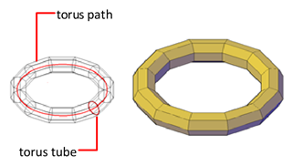
Create a ring-shaped solid that resembles the inner tube of a tire.

A mesh torus has two radius values. One value defines the tube. The other value defines the path, which is equivalent to the distance from the center of the torus to the center of the tube. By default, a torus is drawn parallel to and is bisected by the XY plane of the current UCS.
A mesh torus can be self-intersecting. A self-intersecting mesh torus has no center hole because the radius of the tube is greater than the radius of the torus.
Use the DIVMESHTORUSPATH and DIVMESHTORUSSECTION system variables to set the default number of divisions for a mesh torus.
After a mesh primitive is created, the current level of smoothness for the object can be modified.
Torus Creation Options
The Torus option of the MESH command provides several methods for determining the size and rotation of the mesh tori you create.
- Set the size and plane of the circumference or radius. Use the 3P (Three Points) option to define the size of the mesh torus anywhere in 3D space. The three points also define the plane of the circumference. Use this option to rotate the mesh torus as you create it.
- Set the circumference or radius. Use the 2P (Two Points) option to define the size of the mesh torus anywhere in 3D space. The plane of the circumference matches the Z value of the first point.
- Set the location to be tangent to two objects. Use the Ttr (Tangent, Tangent, Radius) option to define points on two objects. Depending on the specified radius distance, the path of the torus is located as near as possible to the tangent points you specify. You can set up tangency with circles, arcs, lines, and some 3D objects. The tangency points are projected onto the current UCS. The appearance of tangency is affected by the current level of smoothness.