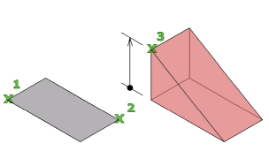
Creates a 3D solid wedge.
Access Methods
Tool Sets:
.

Menu: .
Summary
The direction of the taper is always in the positive X-axis direction of the UCS.

List of Prompts
The following prompts are displayed.
Specify first corner or [Center]: Specify a point or enter c for center
Specify other corner or [Cube/Length]: Specify the other corner of the wedge or enteran option
If the other corner of the wedge is specified with a Z value that differs from the first corner, then no height prompt is displayed.
Specify height or [2Point] <default>: Specify the height or enter 2P for the 2 Point option
Entering a positive value draws the height along the positive Z axis of the current UCS. Entering a negative value draws the height along the negative Z axis.
Center
Creates the wedge by using a specified center point.

- Cube
-
Creates a wedge with sides of equal length.

- Length
-
Creates a wedge with length, width, and height values you specify. The length corresponds to the X axis, the width to the Y axis, and the height to the Z axis. If you pick a point to specify the length, you also specify the rotation in the XY plane.

Cube
Creates a wedge with sides of equal length.

Length
Creates a wedge with length, width, and height values you specify. The length corresponds to the X axis, the width to the Y axis, and the height to the Z axis.

2Point
Specifies that the height of the wedge is the distance between the two specified points.