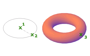
Creates a donut-shaped 3D solid.
Access Methods
Tool Sets:
.

Menu: .
Summary
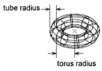
You can create a torus by specifying the center, then the radius or diameter of the torus, and then the radius or diameter of the tube that surrounds the torus. You can control the smoothness of curved 3D solids, such as a torus, in a shaded or hidden visual style with the FACETRES system variable.

List of Prompts
The following prompts are displayed.
Specify center point or [3P/2P/TTR]: Specify a point (1) or enter an option
When you specify the center point, the torus is positioned so that its central axis is parallel to the Z axis of the current user coordinate system (UCS). The torus is parallel to and bisected by the XY plane of the current workplane.
Specify radius or [diameter] <default>: Specify a distance or enter d

3P (Three Points)
Defines the circumference of the torus with three points that you specify. The three specified points also define the plane of the circumference.
2P (Two Points)
Defines the circumference of the torus with two points that you specify. The plane of the circumference is defined by the Z value of the first point.
TTR (Tangent, Tangent, Radius)
Defines the torus with a specified radius tangent to two objects. The specified tangency points are projected onto the current UCS.
Radius
Defines the radius of the torus: the distance from the center of the torus to the center of the tube. A negative radius creates a solid shaped like an American football.
- Radius
-
Defines the radius of the tube.
- Diameter
-
Defines the diameter of the tube.
