- If necessary, open the parametric MvPart in Content Builder.
- In the part browser, right-click Symbol and Annotation Plane, and click Visible. Note: Although this step makes the plane visible in the drawing area, its position on the Z axis in the World Coordinate System (WCS) is high above the WCS origin, so you might need to zoom out to view the plane. You can also change the position of the plane if desired.
- Right-click Symbol and Annotation Plane, and click Set View.
This changes the view direction to Top (plan) view, which is the default view for the plane as well as the most common view for drawing schematic symbols. However, you can select any view that is helpful for drawing the geometry.
- Create the schematic symbol using parametric geometry, constraints, and dimensions.
First, use the model geometry that changes with part size to create point references and projected geometry on the Symbol and Annotation plane. Next, create the symbol geometry on the plane. Finally, add constraints and/or dimensions so that the symbol changes accordingly when the part size changes.
To access the necessary commands, expand Symbol and Annotation Plane, right-click Parametric Graphics, and use the commands on the context menu, as follows. Click Add Geometry, and then click Point Reference.

Symbol and Annotation Plane context menu
To quickly generate the geometry of the model outline on the Symbol and Annotation plane, you can right-click the plane in the part browser, and select Part Boundary. You can use the outline geometry as a guide for the symbol geometry. When you are done, turn off Part Boundary to remove the outline geometry from the plane because it does not change in size.
Tip: Use the Isolate Plane Contents, Hide Plane Contents, and End Object Isolation commands on the context menu of a plane to show or hide the geometry on the plane. - After you have drawn the symbol geometry and added the necessary constraints and dimensions, verify that when the part changes in size, the symbol changes in size in the same way:
- In the part browser, expand Model Parameters, right-click a parameter, and click Edit.
- In the Model Parameters dialog box, modify the values of the parameters for the model, and click Close.
- Examine the changes to the model and symbol in the drawing area.
- If desired, add annotation to the schematic symbol.
- If desired, specify the use of the schematic symbol instead of a model-generated view in 1-line and 2-line display representations in Top (plan) view:
- In the part browser, click
 .
. - In the Options dialog box, click Display Symbol In Plan View, and click OK.
- In the part browser, click
- In the part browser, click
 (Save Part Family).
 - Click
 to close the part browser.
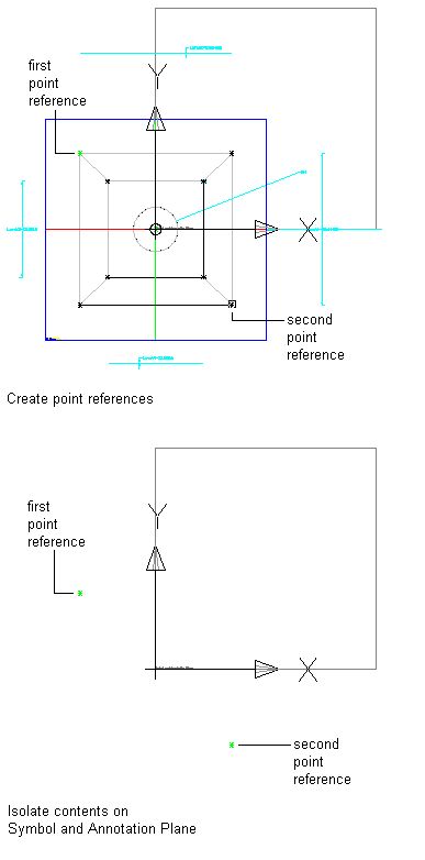
As an example, the following illustrations show how to create a parametric schematic symbol for an air diffuser. First, to align the edges of the symbol with the edges of the diffuser, point references are created on the Symbol and Annotation plane using 2 of the corner points on the diffuser. Then, for better viewing, the contents of the Symbol and Annotation plane are isolated. At this point, the 2 point references are the only geometry on the plane.

Next, using the point references to specify the corner points, a rectangle is drawn to represent the schematic symbol.

Finally, to cause the symbol to scale proportionally with the diffuser, the corner points of the symbol rectangle are constrained to the underlying point references. Because the point references are based on the corner points of the model, this ensures the symbol and the model remain aligned. You can also accomplish this by adding dimensions to the symbol and setting their values to the names of the corresponding model dimensions. This ensures the symbol dimensions change when the model dimensions change.