In this exercise you use Rubbersheet to correct a distorted image of a scanned drawing.
The image in this exercise was distorted in the reproduction process and then scanned. You draw a rectangle to represent the new border for the image and then use Rubbersheet to stretch the image to fit the rectangle. You use the Triangular rubbersheet method in order to have the points move exactly to their desired locations.
Related Exercises
Before doing this exercise, ensure that AutoCAD Raster Design toolset options are set as described in the exercise Exercise A1: Setting AutoCAD Raster Design Toolset Options.
Exercise
- In the
..\Program Files\Autodesk\ApplicationPlugins\RasterDesign2024.Bundle\Contents\Tutorials\Tutorial2 folder, open the drawing file
Scanned_05.dwg.
Create a temporary vector border as a guide
- Draw a vector rectangle starting at 0,0 and extending to 805,565.
Set up viewports
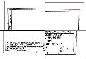
In this lesson, you rubbersheet the image using four control points. A four viewport configuration has been setup to show both the raster and temporary vector border. Each of the four viewports is zoomed in so that you can easily pick the four points.
- On the ribbon, click
View tab
 Model Viewports panel
  Named
Named
 . In the Viewports dialog box, select the viewport named
TU_rubbersheet and click OK.
- To display the
Rubbersheet - Set Control Points dialog box, on the ribbon, click
Raster Tools tab
 Correlate panel
  Rubbersheet
 .
.
Select four control points
For this process you use four control points. Each control point consists of a source and destination pair. The image was originally positioned so that both the lower-left corner of the raster border and the new border you drew, are located at (0,0). You can use the anchor to have the source and destination points be the same for the corner at (0,0). When you finish selecting the four control points they are listed in the Rubbersheet - Set Control Points dialog box.
- Click the Add Points button.
- At the Command prompt, enter 0,0 for the source point and enter a to anchor the destination point.
- Click in the upper-left viewport to make it active. Select the corner of the raster border as the second source point.
- Click OSNAP on and select the upper-left corner of the vector border for the second destination point.
Note: Click OSNAP off before selecting each source raster point, then click OSNAP on to select the destination vector point.
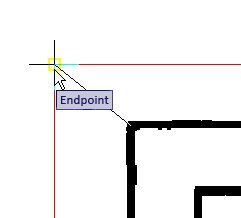
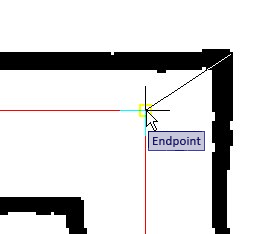
- Click in the upper-right viewport to make it active. Select the corner of the raster border as the third source point.
- Select the upper-right corner of the vector border for the destination point.
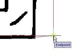
- Click in the lower-right viewport to make it active. Select the corner of the raster border as the fourth source point.
- Select the lower-right corner of the vector border for the destination point.
- At the Command prompt, enter
d to end the selection process. The
Rubbersheet - Set Control Points dialog box redisplays and the points are listed.
Set the rubbersheet method and preview the results
You use the Triangular rubbersheet method for this example. This method causes the four corners to go exactly to the specified destination points. You can verify the results using the Preview button. Since you are using the Triangular method, areas outside the cluster of control points are discarded after the rubbersheet.
Note: If you want to maintain the original image size despite the changes to the raster border in the image, additional control points can be anchored at each corner of the image frame. - In the Method area, click Triangular.
- Click the
Preview button. A preview of the rubbersheet is shown. The full preview is shown in the last active viewport and the other viewports show the preview in their respective zoom levels.
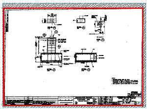
The preview shows the extents of the result in red and the extents of what makes that area up in cyan. The hatched area between the cyan extents and the original frame of the image are discarded in the final result.
- Right-click or press
Enter to exit the preview.
Rubbersheet the image
- Click the Export button to display the Export dialog box. Name the file FoundationDetail_05.txt. Note where the file is being saved, then click Export to finish the export. If you want to repeat the rubbersheet operation with different settings you can use this file as a starting point.
- Click OK. The rubbersheet processes and the Rubbersheet-Set Control Points dialog box closes.
- On the ribbon, click
View tab
 Model Viewports panel
  Named
Named
 . Then restore the viewport named
Rubbersheet Final Result.
- Erase the vector border.
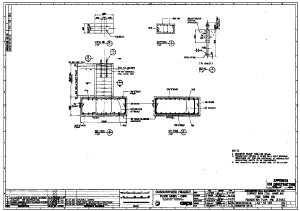
- Close the drawing without saving any changes to the drawing or image.