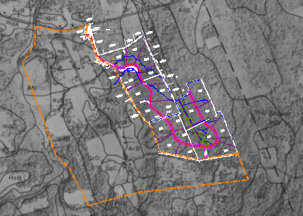
In this exercise you use a world correlation file to insert an image of a soils map.
Using a correlation file, such as a world file or a resource file, is one of several options for specifying the insertion point, rotation, and scale when you insert an image.
Also in this exercise, you work with the setting for image units in relation to drawing units.
Related Exercises
Before doing this exercise, ensure that AutoCAD Raster Design toolset options are set as described in the exercise Exercise A1: Setting AutoCAD Raster Design Toolset Options.
Exercise
- In the
..\Program Files\Autodesk\ApplicationPlugins\RasterDesign2024.Bundle\Contents\Tutorials\Tutorial5 folder, open the drawing file
Map_05.dwg.
Choose an image to insert
- To display the Insert Image dialog box, on the ribbon, click
Raster Tools tab
 Insert & Write panel
  Insert
 .
.
- In the Insert Image dialog box, from the Files of Type list, choose TIFF.
- If necessary, navigate to the ..\Program Files\Autodesk\ApplicationPlugins\RasterDesign2024.Bundle\Contents\Tutorials\Tutorial5 folder.
- Select the image file Soilsmap_world_01.tif.
- On the Views menu verify that Preview and Information are checked. This displays a preview window and a list of information about the image.
- Review the values shown for each parameter.
Insert the image using a world correlation file
- Under Insert Options, select the Insertion Dialog option. Also make sure that Show Frames Only and Zoom To Image(s) boxes are cleared.
- Click
Open to display the
Image Correlation dialog box. Click the Source tab.
AutoCAD Raster Design toolset detects that a world correlation file (soilsmap_world_01.tfw) is associated with this image. The dialog box shows the insertion point, rotation, and scale specified in the correlation file.
- Click the Insertion tab.
Note the Drawing Units are specified as Meters. The image must use the same setting for proper correlation.
- Click the Modify tab. Under Units, note that the Image Units can be changed here.
- Ensure that the image units are set to Meters to match the drawing units.
Tip: In this step, you are setting the image units for this insertion only. In your real work with images, if you ever want to change the default setting for all insertions, on the ribbon, click Raster Tools tab
 Insert & Write panel
  Dialog box launcher (
 ). In the Raster Design Options dialog box, click the Image Defaults tab. On this tab you can set both horizontal units (under Density) and vertical units.
- Click Apply to see the image displayed in the drawing, then click OK to finish the insertion process.
- If the vector line work is not displayed on top of the image, enter
REGEN to correct the display order.

- Close the drawing without saving changes.